Continue to Site

Welcome to EDAboard.com

Welcome to our site! EDAboard.com is an international Electronics Discussion Forum focused on EDA software, circuits, schematics, books, theory, papers, asic, pld, 8051, DSP, Network, RF, Analog Design, PCB, Service Manuals... and a whole lot more! To participate you need to register. Registration is free. Click here to register now.

Help with transistor switch,pls.

Status
Not open for further replies.

louarnold

Member level 2
Joined
Jun 2, 2010
Messages
52
Helped
0
Reputation
0
Reaction score
0
Trophy points
1,286
Location
Canada
Activity points
1,754
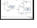
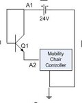
The included image shows the schematics for a scooter's enable line.
EnableSwitch.jpg

Figure 1 shows its normal use; the switch enables the scooter's drive system. Note that there seems to be no appreciable current passing through the switch. I checked it with an in-line ammeter.

I tried to substitute a transistor for the switch (Figure 2), but it doesn't work. (The 5V simulates an output of a micro-controller.) In fact, I can short out all the resistors and it still won't work; the emitter voltage always reads 3.6V.

What's the solution?
 

My guess: Your transistor is in active region. To behave as a switch it should be in saturation region.
 

For maximum response the NPN transistor should have a plain wire as the emitter leg (lower).

The load goes in the collector leg (upper).

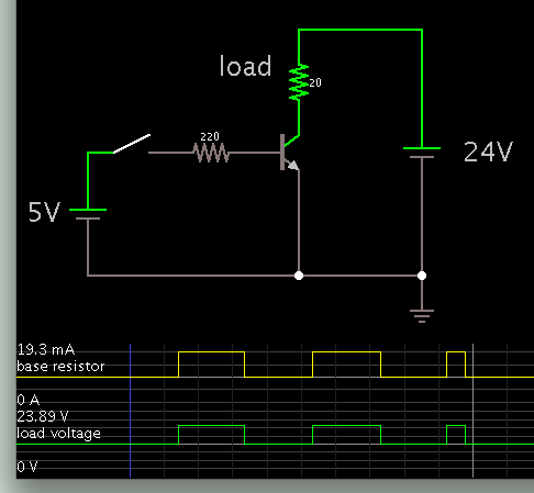
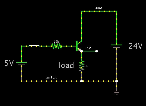
Screenshot:

7556757800_1354520095.png
 

Your circuit can only pull the emitter to around 3V to 4V as you have found. You get the 5V from the microcontroller, then the base resistor volts drop then the base-emitter volts drop - hence your 3.6V.

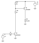
If you want a 24V drive (which it appears you do) you need two transistors - a PNP doing the switching and an NPN as a level shifter to drive the PNP base.

Keith

- - - Updated - - -

Image attached
 

Attachments

  • Level shifter.gif
    Level shifter.gif
    3 KB · Views: 122

Keith's method with 2 transistors has the advantage of (a) controlling more amperes through the load, and (b) reducing the required current from the microcontroller.

Screenshot:


- - - Updated - - -

After posting I see we were both devising a simulation at the same time.
 

Brad,

The problem with your first circuit is that it assumes the load can be connected to +24V and the ground switched. I assumed that was not the case. Otherwise your single transistor would be fine because the original post says the current requirement is very small.

Keith
 

Untitled.jpg
Hi Brad,
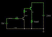
If you change your circuit as attached , i think it would work..
 

View attachment 83850
Hi Brad,
If you change your circuit as attached , i think it would work..

I believe the transistor would act as a shunt.

The load will turn on when no signal is coming from the left...

and it will turn off (or receive less power) when there is a signal.

There are situations where you would want equipment to do this. However it does not match the action in Fig. 1.
 
My guess: Your transistor is in active region. To behave as a switch it should be in saturation region.
No, shorting the resistors - replacing with plain wire - would put them into saturation. But that doesn't work.


Brad,

The problem with your first circuit is that it assumes the load can be connected to +24V and the ground switched. I assumed that was not the case. Otherwise your single transistor would be fine because the original post says the current requirement is very small.

Keith
The 1st circuit is Figure 1. There is NO problem with that circuit; that is the way the mobility chair (scooter) was built. It is a key-switch on the scooter's tiller. Closing the switch applies 24v (battery voltage) to the drive-enable input (A2) of the drive controller. The current is so small that I cannot measure it even on the 200uA scale. In that sense there is no load; its simply a very high-resistance input.

- - - Updated - - -

For maximum response the NPN transistor should have a plain wire as the emitter leg (lower).

The load goes in the collector leg (upper).

Screenshot:

7556757800_1354520095.png
No, you have changed the circuit. Look at Fig 1 again. That is the way the scooter was built. A2 is the ENABLE input to the drive controller. Somehow 24 volts has to be applied to that input. The current is not measurable even at 200uA on the meter.

- - - Updated - - -

The cause of your problem has already been explained here: https://www.edaboard.com/threads/273382/#post1172309 as well as various potential solutions.

Keith
I will decide if the problem has been explained. I don't need a moderator to tell me.

- - - Updated - - -

I believe the transistor would act as a shunt.

The load will turn on when no signal is coming from the left...

and it will turn off (or receive less power) when there is a signal.

There are situations where you would want equipment to do this. However it does not match the action in Fig. 1.
Now I can hear you thinking. The transistor SHOULD act as a shunt, but when the input at the left goes up. That's when the transistor goes into saturation - ie turns on.
In fact, it works when you tie the collector and base to 24V, and the emitter to the A2 Enable input. But of course there can be no control from a separate micro-controller. See the image below:
ShuntQ.jpg
If you put the ammeter in series with the emitter, there is still NO current.
 

Sorry, I didn't know how much current was needed through the controller (load).

Here is a screenshot simulating the circuit in post #1. No special resistor values, just typical. It shows the volt level on the load is 4V.

2620520000_1354561889.png


This is one of those cases where what we think looks like it should work, doesn't. It frequently happens.

By experimenting with NPN and PNP types, and with different arrangements, you should find you can achieve the result you want.

- - - Updated - - -

I believe Keith's circuit in post #4 will do the job.
 

I will decide if the problem has been explained. I don't need a moderator to tell me.
Your response is rather rude considering people are trying to help you and you are ignoring valid responses and making basic errors in your circuits which have been politely explained.

Your latest reply also contains errors but I guess you don't want to here those from a "moderator".

Keith
 

No, shorting the resistors - replacing with plain wire - would put them into saturation. But that doesn't work.
Hi
What makes you think that shorting the resistors will put the BJT in saturation? On the contrary, it will push the BJT even further away from saturation into active region. One of the simpler test is to see that the reverse bias of the base collector junction will become even larger. With 19V reverse bias across base-collector junction, the transistor cannot remain in saturation.

Coming back to your problem, if I understand correctly, you have to connect/disconnect a large load resistance to a 24V supply. Probably, if you connect your load parallel to the 100 ohms (Rload) resistance in Keith's circuit, it should solve your problem.
 

Status
Not open for further replies.

Part and Inventory Search

Welcome to EDABoard.com

Sponsor

Back
Top