Continue to Site

Welcome to EDAboard.com

Welcome to our site! EDAboard.com is an international Electronics Discussion Forum focused on EDA software, circuits, schematics, books, theory, papers, asic, pld, 8051, DSP, Network, RF, Analog Design, PCB, Service Manuals... and a whole lot more! To participate you need to register. Registration is free. Click here to register now.

help with timer circuit

Status
Not open for further replies.

mohsen 2012

Member level 4
Joined
Jul 3, 2012
Messages
70
Helped
0
Reputation
0
Reaction score
0
Trophy points
1,286
Activity points
1,796
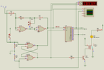
Hello guys , i build this timer circuit :

http://www.electronics-lab.com/projects/oscillators_timers/008/002_Schematic_th.png

**broken link removed**

the problem is when i set the jumper at 120 second the relay switch turned ON during a few seconds only !!
i replace the variable resistor with a 3M9 fixed resistor but the circuit work for a 5 seconds !!!
the same problem with all jumpers when i set it to 2 hours it work for a 1 minute!!
Please help me and thanks
 
Last edited by a moderator:

The pic isn't very clear but it looks like your C1 is 22nF instead of 220nF. This will make your delay 10 times shorter.
Is the date on the cmos is 1980 ? they must be very valuable now.
 
Last edited:

No , the capacitor value is 220nf the code marked on the capacitor is .22m63
 

There is no such thing as .22m63. Microfarads is always the micro symbol not the letter m.
Your oscillator runs too fast because the capacitor value is too low.
Your camera is hopeless but I think the capacitor shows 22n63 which is 22nF, 63V. Usually the tolerance (J is 5%, K is 10% and M is 20%) is shown like in this photo of a 22nF 10% 63V capacitor:
 

Attachments

  • capacitor.png
    capacitor.png
    39.8 KB · Views: 65

I guess you don't have another 0.22uF cap. What you can do is to de-solder C3 0.1uF and solder it in parallel to C1 and test if you get better timing.
I recommend to do it before audioguru gets really angry.
 

look at the value shown in multimeter 11157005_786962598055004_1519372255_n.jpg
this is the same capacitor used in the circuit !!
 

The circuit seems OK and it works on the proteus sim. To trouble shoot, I would use a watch to compare the basic clock pulse time from the 4001 osc. is correct.

For easy calculation, I set it to 500mS so what came out from Q3 is 8 second pulse. You have to make sure that this timing is correct before moving on to the other 4020 clock divider's pulses.
 

Attachments

  • 4020 timer.PNG
    4020 timer.PNG
    49.6 KB · Views: 74

Status
Not open for further replies.

Part and Inventory Search

Welcome to EDABoard.com

Sponsor

Back
Top