Continue to Site

Welcome to EDAboard.com

Welcome to our site! EDAboard.com is an international Electronics Discussion Forum focused on EDA software, circuits, schematics, books, theory, papers, asic, pld, 8051, DSP, Network, RF, Analog Design, PCB, Service Manuals... and a whole lot more! To participate you need to register. Registration is free. Click here to register now.

Help with simple project

Status
Not open for further replies.

beerdrinker

Newbie level 4
Joined
May 15, 2013
Messages
5
Helped
0
Reputation
0
Reaction score
0
Trophy points
1,281
Activity points
1,319
Hello this is my first post in your forum and I appreciate your help to design/ create a simple project.
The ideia is build two auxiliary braking light's to my motorcycle topcase.

My idea is to have both leds lighted up at about 50% of their power as rear running light and at full power when the brakes are activated.

Alternator info: 14 V/310 W at 5,000 r/min
I will use: 2 X 10W LED chip (9-12V; 1000mA each)

I stop studing electronics at about 15 years ago, so my knowledge is almost gone.

Thank you in advanced for your help!
 

The voltage drop across the LEDs does not change much with their operating current. Their brightness does vary with the current. So if we say your LEDs drop 9V, you have 14V available, so in full power mode you need a (14 - 9) = 5V/1A = 5 ohms. And in their low power mode, 5/.5 = 10 Ohms. If your LEDs are 12V ones then the resistor values are 2 and 4 ohms respectively.
So the first step is to find out what the actual LED voltages are, or you will have to fiddle about to select resistors on the basis of the actual current.
Frank
 
thank you for your help.
I search the specifications of the leds, here they are:
Voltage: 9V-12V
Forward Voltage: 10V
Power : 10 watt
Forward Current : 1000mA

How do I switch from running to brake lights? Just occured me a relay. .Is ther any other whay? I Need a simple, reliable and compact scheme for this.

Thank you for you help

**broken link removed**
 

you can use an NPN transistor as a switch, you can put one transistor in series with each resistor ( between resistor and ground),
and in each situation you switch on the other will be OFF
 
Hello, thank you for your help.
I read here about Using a transistor as a switch, but I'm not sure I fully understand...
I don't understand how do I connect the transistors in order them to work...
Sorry, can you please explain like I'm 10 Years old?...

I really appreciate your patience.
Thank you!

edit: and what tipe of transistor should I use?
 

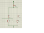
here is an example using NPN, if you apply 12V on Q1 and GND on Q2, current will flow throught R1, if you apply GND to Q1 and 12V to Q2, current will flow throught R2,
simple circuit.png
 
Thank you for your example and patience.
I don't undertand how it will switch, as I will have, basicaly, two power sources:
one power source, light up the leds at 50%
one power source to light the leds at 100%

I need something switching from the always up running lights (50% power) to brake lights (100% power) when brake is applied.
 

The easiest way is to connect the pair of LEDs with their 50% resistors (14-10) = 4/.5 = 8 ohms straight of the ignition wiring, so the LEDs are on 50% when the engine is running. Now wire a diode to the brake lights (anode to lights) to its cathode connect two four ohm resistors, one to each LED.
Theory :- without the diode, the voltage on the LEDs in normal running would backfeed and make the brake light bulb glow, the diode stops this. the diode must be rated at 2 A and 12V - cheap device.
Frank

Thank you for your reply,
This method is more reliable than the relay?
example
running lights: connect the leds in parallel.
brake lights: the relay change the circuit to full power on LED's

Thank you for your help!
 

Well a diode cost less then a relay and is more reliable. The only point of contention is if the existing brake light switch can handle the extra current. You have to have the four resistors anyway.
frank
 
Last edited:

Status
Not open for further replies.

Part and Inventory Search

Welcome to EDABoard.com

Sponsor

Back
Top