Continue to Site

Welcome to EDAboard.com

Welcome to our site! EDAboard.com is an international Electronics Discussion Forum focused on EDA software, circuits, schematics, books, theory, papers, asic, pld, 8051, DSP, Network, RF, Analog Design, PCB, Service Manuals... and a whole lot more! To participate you need to register. Registration is free. Click here to register now.

help with RGB led driver --- how to turn on stacked transistors?

Status
Not open for further replies.

NuNDoe

Junior Member level 1
Joined
Jan 19, 2011
Messages
15
Helped
0
Reputation
0
Reaction score
0
Trophy points
1,281
Activity points
1,435
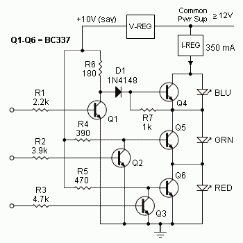
I'm designing a RGB LED circuit that uses a stacked transistor topology. There are 3 LEDs, and each LED is paired with a transistor in parallel... these 3 LED/transistor pairs are stacked together and connected to a constant current driver. To turn on any LED, its corresponding transistor is turned off, so all current flows through the LED. To turn an LED off, the corresponding transistor is turned on, effectively shunting the current away from the LED.

so the question is, with this stacked transistor topology, is there an easy way to control the 3 transistors using logic level outputs from a microcontroller? what additional circuitry do I need to transfer the logic level (5V) output to something that can turn on/off even the transistor at the very top?

with the constant current driver, one can see the voltage at the top LED may vary, depending on how much LEDs are turned on, at most it will be the Vf's of all 3 LEDs, and at a minimum, it will all be shunted to 0V. therefore, the collector voltage of each transistor may also vary...

my initial idea was to have another transistor or mosfet tied to a higher voltage (like 12V input) and driving that with logic and feeding the 12V onto the base of the transistor... however, fluctuations of the input voltage may also effect the brightness of the LEDs...

thanks!

rgbdriver.jpg
 

that is an interesting way, I checked the datasheet and it seems the turn on/turn off speed may be too slow, I'll check out other opto-isolators and see if I can find something with the bandwidth I need. are there any solutions using just basic analog circuit elements?
 

If you feed each base via a high value resistor to the LEDs Vcc + 1v, then all the transistors are "on", i.e. the LEDs are off. Now diverting the base current from any transistor to earth, will turn off that transistor. Your turning off transistor needs to be rated at Vcc(LED) +1V.
Frank
 

If you feed each base via a high value resistor to the LEDs Vcc + 1v, then all the transistors are "on", i.e. the LEDs are off. Now diverting the base current from any transistor to earth, will turn off that transistor. Your turning off transistor needs to be rated at Vcc(LED) +1V.
Frank

the problem in this application is the high side of the 3 LEDs will vary based on which LEDs are shunted (since we're using a constant current source and not a constant voltage --- so there is no VCC per se). so if all 3 LEDs are ON, the voltage of the highside is 3xVf, and if all 3 LEDs are OFF (all transistors shunted) we should only have a highside of a few mV... I guess I could use a supply that is higher than all 3 LED's Vfs, but that will require an additional voltage regulator just to supply the transistor's pull up voltage... I'd rather do everything at the logic level if possible... IS this possible?
 

I had an idea closely similar to chuckey's earlier today but ran into problems working out realistic component values. I've solved them but it requires a non-logic level supply which you've just indicated that you don't want. It would be rash to say that it's not possible to "do everything at the logic level", but it's unlikely. Let's consider just one factor:

Suppose the bottom and the middle LEDs are to be lit up and the top one turned off. One red and one green LED in series will drop roughly 5V. This places the emitter of the top transistor at that voltage above ground. To turn the transistor on (and its LED off), the base needs to be at +5.8-6V. That's already above logic level even without any additional drop in other components.

In any case, while you're saying that the LED chain is supplied with a current source, even a current source has to have a finite voltage source in the real world. I think you'll have to either revise your stack design or accept that you have to have a non-logic level supply.
 

thank you for the response, i do agree that the current source will source more than 5V if multiple LEDs are on. I was using a circuit simulator and trying to tie some transistors onto the highside to feed that voltage to the LED-transistor pairs --- only problem is that the current source (which is trying to supply 350mA) will now be splitting off some current to drive the other transistors... which means the LEDs' current will drop.

it looks like i will have to accept the fact that I'll need an additional voltage source (let's say 9V) and then use that voltage to drive the 3 LED-transistor bases via another set of 3 transistors...
the only issue I see with that is (maybe I'm being knit-picky) the relative base-emitter voltage of any LED pair transistor will change depending on how many LEDs are turned on at the moment. I guess as long as the Vbe is making the transistor operating in saturation then I'm OK right? I just don't want the current of any individual LED to fluctuate by much when other LEDs are switched on/off

I had an idea closely similar to chuckey's earlier today but ran into problems working out realistic component values. I've solved them but it requires a non-logic level supply which you've just indicated that you don't want. It would be rash to say that it's not possible to "do everything at the logic level", but it's unlikely. Let's consider just one factor:

Suppose the bottom and the middle LEDs are to be lit up and the top one turned off. One red and one green LED in series will drop roughly 5V. This places the emitter of the top transistor at that voltage above ground. To turn the transistor on (and its LED off), the base needs to be at +5.8-6V. That's already above logic level even without any additional drop in other components.

In any case, while you're saying that the LED chain is supplied with a current source, even a current source has to have a finite voltage source in the real world. I think you'll have to either revise your stack design or accept that you have to have a non-logic level supply.
 

rgbdriver.jpg here's an update to what i have... which is basically like the above people suggested, i'll have to have an additional 9V source...
if anyone has a solution where I don't need an additional voltage source that would be good (and if it has to use the power provided by the current source, it needs to not draw much current, only a few mA at most)... would really appreciate any additional inputs. thx everyone!
 

There is also the option to use a laser/led driver with multiple channels and TTL-inputs, typical used to drive RGB laser diodes up to 1A per channel - like with the iC-HG. Actual it is a current switch and the current can be controlled by a separete input (also for modulation). On/off switching is also very fast if needed and level shifting is not needed. The data sheet link: https://www.ichaus.biz/HG_datasheet_en
 

thank you for that suggestions, it is a solution but i cannot use a driver like that because the pincount, complexity, and cost is more than what this project will allow for. using this topology essentially just uses a single channel LED driver and you're using the transistors to shunt the LEDs to control multiple channels.
 

How about the circuit below? This scheme does not divert anything from the 350mA current source for the LEDs but does consume additional power from the main power supply. Max consumption by the switching circuit is about 100mA when all LEDs are ON. The main drawback is the minimum supply voltage requirement. I chose the BC337 because of its high minimum gain and a rating high enough to sink 350mA comfortably. If we use the BC337-40 sub-type, all the resistors can be at least doubled in value and current consumption will be halved.

72_1325054755.png
 

Free idea for further developing and simulation...............

3-Col_Led_Mux.jpg
 

Status
Not open for further replies.

Similar threads

Part and Inventory Search

Welcome to EDABoard.com

Sponsor

Back
Top