Continue to Site

Welcome to EDAboard.com

Welcome to our site! EDAboard.com is an international Electronics Discussion Forum focused on EDA software, circuits, schematics, books, theory, papers, asic, pld, 8051, DSP, Network, RF, Analog Design, PCB, Service Manuals... and a whole lot more! To participate you need to register. Registration is free. Click here to register now.

help with pic18F4550 crystal

Status
Not open for further replies.

behranghm

Member level 1
Joined
Feb 12, 2006
Messages
35
Helped
0
Reputation
0
Reaction score
0
Trophy points
1,286
Activity points
1,626
pic18f4550 configuration bits

i am using pic18F4550 in a fairly simple circuit for the first time and i am having severe problems with it's oscillator in every mode. i have tried a 20 Mhz crystal with a whole range of capacitors with a variety of fuse programming modes for the oscillator. Still the oscillator isn’t working or is not stable. Any clue? Any help?
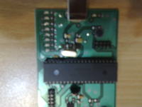
 

ccs pic18f4550

Do you use a 20-22pF as usual?
What X-tal type was used?
 

pic18f4550 ccs

Use 22pF capacitors from XTAL I/O to ground. and which fuse settings your using ?.
 

    V

    Points: 2
    Helpful Answer Positive Rating
pic18f crystal

See page 25 for OSCILLATOR CONFIGURATIONS
https://ww1.microchip.com/downloads/en/DeviceDoc/39632D.pdf

PIC18F2455/2550/4455/4550 devices can be operated
in twelve distinct oscillator modes. In contrast with previous
PIC18 enhanced microcontrollers, four of these
modes involve the use of two oscillator types at once.
Users can program the FOSC3:FOSC0 Configuration
bits to select one of these modes:


In HS, HSPLL, XT and XTPLL Oscillator modes, a
crystal or ceramic resonator is connected to the OSC1
and OSC2 pins to establish oscillation.
The oscillator design requires the use of a parallel cut
crystal.
Use of a series cut crystal may give a frequency
out of the crystal manufacturer’s specifications.


An internal postscaler allows users to select a clock
frequency other than that of the crystal or resonator.
Frequency division is determined by the CPUDIV
Configuration bits. Users may select a clock frequency
of the oscillator frequency, or 1/2, 1/3 or 1/4 of the
frequency.
 

pic18f 4 20 mhz usb fuse settings

I don’t know what sort of crystal exactly it is, seems to be a quartz crystal though, I changed the crystal from 20Mhz to 8Mhz with 15pF capacitors. I tried all the possible fuse settings, I tried a simple code on the PIC and it worked so and so (with the fuse settings of XT) although I can’t still say if the oscillator is running properly. But when I test it with the CDC code I get no results from the PC. I have been through the data sheet and I have the PDF a part of which you have provided here.
 

pic18f4550 postscaler

How long are the PCB tracks from your MCU to your XTAL ???.. Make a Photo !.
 

pic18f + ccs c + oscillator problem

the tracks from the crystal to the microcontrollers are no longer than 10mm.

Added after 1 minutes:


pic18f usb cdc interrupt

hi, i think you have an oscillator problem due to large or other pcb track problems. try putting a 1 mega ohm resistor across the xtal. Please also tell us all the configuration settings you use and your settings should be for HS !!.

Did you try the internal RC to see if this would work ?.

How do you know the osc is not stable ?. are you measuring it with an oscilloscoop ?. if so put your probe at 10 Meg setting and try again.
 

crystal needed for pic18f

Easy problem to fix with access to an ICD like the ICD2 or PICkit2
The PCB appears to be professionally made and the schematic is correct.
 

pic18f4550 running on 20 mhz

Good hint, I observed the crystal on a Digital oscilloscope and the 8 MHz sine wave is quite nice and stable, although the amplitude is somewhat weak (about 120mv p-p when observed with a 10x probe). Now the last thing I can do is that I put the code and the PCB project for you here. You tell me what I should exactly do with the code or the PCB. I am using Protel DXP and CCS. The code is from the CCS examples for PIC18F4550 I have made virtually no change in it. I am somewhat certain the code is correct cause it works on Proteus 7 Proffessional. Tell me if I should make any modifications with the PCB or the code.
 

pic18f4550 a 20mhz

Good hint, I observed the crystal on a Digital oscilloscope and the 8 MHz sine wave is quite nice and stable, although the amplitude is somewhat weak (about 120mv p-p when observed with a 10x probe). Now the last thing I can do is that I put the code and the PCB project for you here. You tell me what I should exactly do with the code or the PCB. I am using Protel DXP and CCS. The code is from the CCS examples for PIC18F4550 I have made virtually no change in it. I am somewhat certain the code is correct cause it works on Proteus 7 Proffessional. Tell me if I should make any modifications with the PCB or the code.
 

pic18f configuration bits

If I can give you one more hint: Through CCS away and use a real C compiler, CCS is crap of the first kind, with more bugs than features.

Are you sure your capacitors are 20pF ?. Remove them both and measure with your oscilloscoop again. Do one ref measurement by measuring your VCC to see if your measurement is correct ?. You should measure 5V DC !!..

Also measure on both sides of the xtal and the signal should be about the same, with 22pF load capacitors. Do this only with 10x proble setting !. What is your bandwidth of your oscilloscoop ?
 

configuration bits pic18f4550

The oscilloscope is a brand new 100MHz Tektronix with 1Gsapmle/sec. the supply line comes directly from USB bus and it measures precisely 5 volts, now I have been working with other USB peripherals in the same way, notably AVR_CDC and FT232 and I have experienced none of these problems, what alternative do suggest for CCS by the way?
 

pic18f1320 hspll

Hi,

You can use Microchip C18 compiler. Microchip also provides HID and CDC example. You should take a look at the microchip forum under usb section.

Regards,
Franck.
 

pic18f1320 circuit crystal

Hi, As others already told you use C18. The problems you have are not related to CCS though but CCS is a bad compiler (I think you should not even use the term "compiler") They try to do clever but its actually a way of hiding they do not know how to make a real compiler. One example is that re-entrance code is if written is not allowed and suppressed by the compiler without it telling you anything or even giving you the option to allow it. Example: If you have a function your calling in your main and the same function you call in an interrupt routine the compiler will automatically disable all interrupts during the function call in your main routine !!.. This is very stupid since your code can be written in a way that will not be harmful at all (using local declared variables instead of global). You only get a warning which you will ignore as always and your not able to disable this behavior of the compiler. You have: Local variables, Global variables but also static variables, CCS is seeing no difference between : static, local and global variables. Initializing local and static variables sometimes simply does not work even though the C code is perfect. I write C code for 30 years now, so I think I know if I am making an error :).

OK. Back to your problem: Your Scoop is perfect so you measure 1.2V which is way to low for a normal oscillator.. normally some 2.5 V tt is to be expected from 5V supply. Put a resistor of 1M over your xtal and do measure again !.
 

    behranghm

    Points: 2
    Helpful Answer Positive Rating
pic18f4550 pcb

I am also a beginner with the pic18f4550 and I am trying to use it as a USB mouse. I was told I need a crystal of at least 20mhz and from the references below, I believe I need to hook up the circuit like figure 8-7 on this site: https://www.mikroe.com/en/books/picmcubook/ch8/ and page 27 in the manual: https://ww1.microchip.com/downloads/en/DeviceDoc/39632D.pdf

I believe I was told "at least" 20mhz is the requirement... I think my partner purchased 33mhz or so.. microchip does not mention one greater than 20mhz. Can a crystal with > than 20mhz be used? How would I find the capacitance values if so?

Thank you.

-C. Thomas

Added after 13 minutes:

Update: I just found out it's a 24mhz not 33
 

I have the same problem (identical) - with oscillator
Does anyone know what is happening ?

- Put the resistor across the xtal (no result)
 

I have this same issue. But I`ve noticed somethings that should help the experts to solve this:
whenever I put the voltimeter between the ground and one of the 22pf capacitors the clock starts working or if I stay a little while with my finger on that capacitor it also works. Actually it works gradually increasing the speed.

I tried the 1M res across the Xtal and didn`t works and a 1M res across that capacitor but still nothing.

Any other ideas, sugestions??
 

Status
Not open for further replies.

Similar threads

Part and Inventory Search

Welcome to EDABoard.com

Sponsor

Back
Top