Continue to Site

Welcome to EDAboard.com

Welcome to our site! EDAboard.com is an international Electronics Discussion Forum focused on EDA software, circuits, schematics, books, theory, papers, asic, pld, 8051, DSP, Network, RF, Analog Design, PCB, Service Manuals... and a whole lot more! To participate you need to register. Registration is free. Click here to register now.

Help with phase shift in Digital filter in MATLAB

Status
Not open for further replies.

lordgty

Junior Member level 1
Joined
Jul 7, 2010
Messages
19
Helped
1
Reputation
2
Reaction score
1
Trophy points
1,283
Location
Pakistan
Activity points
1,380
I am using fdatool in MATLAB to design digital filter. The sampling rate is 6400 Hz. Cutoff freqq=uency is 100 Hz.THe following is the screenshot:

Untitled.png 
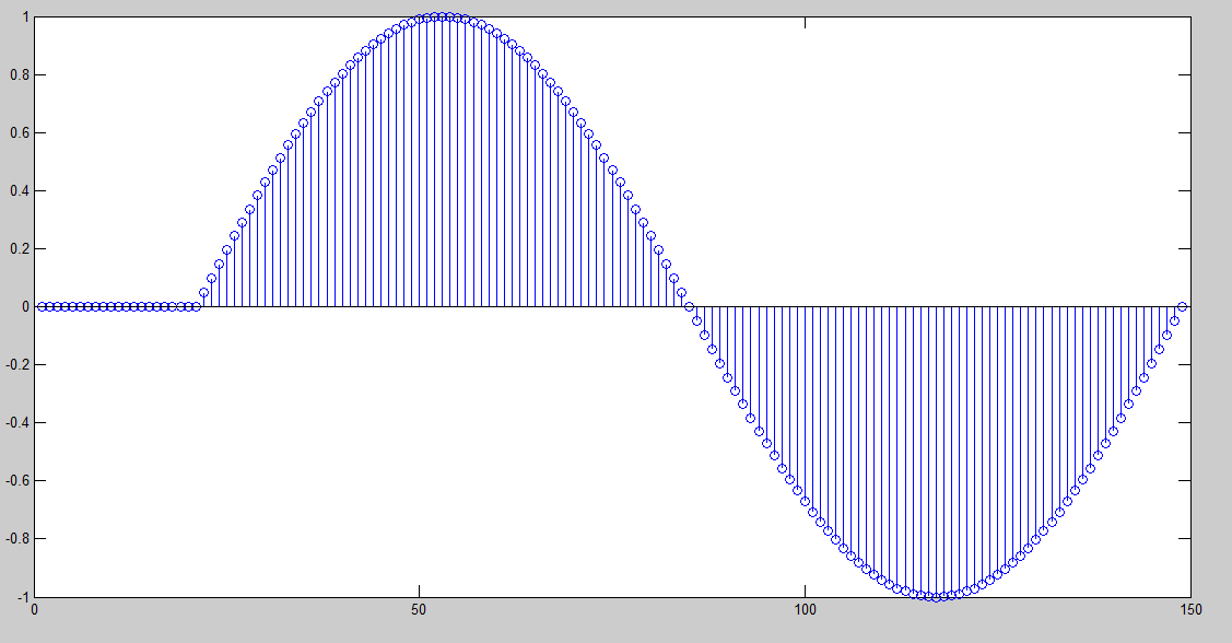
Now the filter info shows that filter has linear phase. The input to the filter is a simple sine wave of 50Hz frequency, shown as this:
Untitled.png 
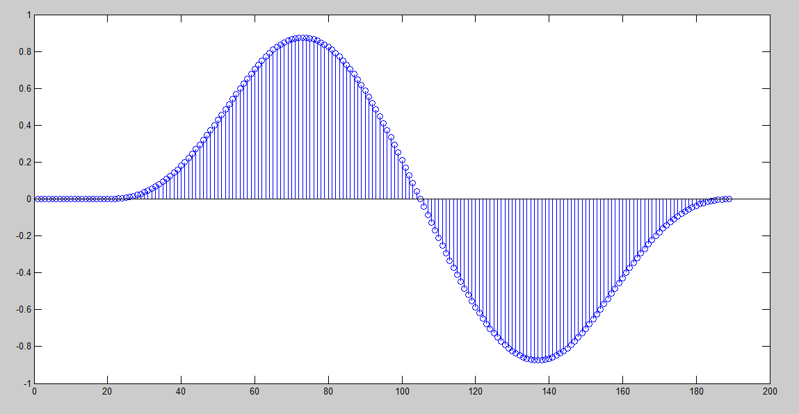
The output of the filter is this:
Untitled.pngThe output looks like distorted, not only phase shifted. How to extract original signal from this output? How to compensate the phase shift so as to get almost exact signal as input?
 

The input to the filter is a simple sine wave of 50Hz frequency
It isn't a "simple sine wave".The input generating the shown output is a single sine cycle, not a continuous sine wave. The output looks respectively "distorted".

The output looks like distorted, not only phase shifted.
According to the nature of FIR filter, the output is delayed by 20 samples, not phase shifted. The only way to "compensate" the filter effect is to delay the original signal, too.
 

Thanks. Yes this is just one cycle, actually i am trying to do frame based processing of signal. I have delayed input by 20 samples like:

However the output is:

Please tell me can i recover the peak value of the input from the output signal?
 

The filter arithmetics uses a tapped delay line so its output grows slowly and reaches maximum at the delay equal to half a length. For 40 order it is 20 samples.
If you dont want distorted signal just take two sinewave periods and remove first from analysis at the output. And dont delay input signal at the filter input, it is sensless.
 

If you dont want distorted signal just take two sinewave periods and remove first from analysis at the output.
This is completely correct and i have verified it. Thanks. Now only thing remaining is the problem with the amplitude of the signal. Input signal has peak equal to 1 whereas output signal has peak of about 0.85. Can i generalize the difference i.e. 0.15 for every signal filtered through this filter?
 

Status
Not open for further replies.

Part and Inventory Search

Welcome to EDABoard.com

Sponsor

Back
Top