Haris Shafiq
Newbie level 2

- Joined
- Aug 1, 2013
- Messages
- 2
- Helped
- 0
- Reputation
- 0
- Reaction score
- 0
- Trophy points
- 1
- Activity points
- 17
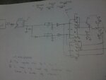
I've designed an H-bridge circuit
(https://obrazki.elektroda.pl/4652666800_1375483001.jpg),
kindly help me out if it has any errors?
Q: someone told me to put boost capacitor between gate and source of high side mosfet when u r running high voltage motor, e.g; 48 volts.
Q: some values are not known by me, so if anyone of u can guide it will be much appreciable.
Q: also, if this circuit has any errors, kindly tell me because I've made this type of circuit for the first time and i don't want to burn any hardware before confirming that it's circuit is OK.
thanks.
- - - Updated - - -
http://obrazki.elektroda.pl/9824587900_1375483000.jpg
its another image of circuit, sorry for the bad image quality, i havnt got any good camera :lol: