Continue to Site

Welcome to EDAboard.com

Welcome to our site! EDAboard.com is an international Electronics Discussion Forum focused on EDA software, circuits, schematics, books, theory, papers, asic, pld, 8051, DSP, Network, RF, Analog Design, PCB, Service Manuals... and a whole lot more! To participate you need to register. Registration is free. Click here to register now.

[SOLVED] help with MC34063A powersupply

Status
Not open for further replies.

help_with_powersupply

Newbie level 6
Joined
Sep 9, 2009
Messages
12
Helped
1
Reputation
2
Reaction score
10
Trophy points
1,283
Location
USA
Activity points
1,414
mc34063a

Hi,
I have to amend an existing circuit consisting of a MC34063A and a P-MOS switch.
It is a downconverter, from 12V to 3.3V/1.5A .

I, like you, do this out of helping and am not being paid. This is for a good cause.

The circuit has a coil which gets extremely hot, so hot, that it kills the neighboring capacitors over time.

Exchanging them is only a temporary fix, they die again after a while.

I cannot use a fan and cannot replace the SMD semiconductors or the coil.

Only capacitors or resistors can be removed/exchanged.
Semiconductors can be piggy packed however.

From what I researched, it is quite a standard design of the MC34063A with a P-MOS transistor for more Amps.

What can be done in general to reduce the heat of the coil?

Is it the efficiency or do these coils just get this hot (60 C, 150 F)?
The capacitors are rated only 5000h, are there types which can last for 3-5 years?

I could make a schematic if it would help.

Thanks in advance for your helpful reply!
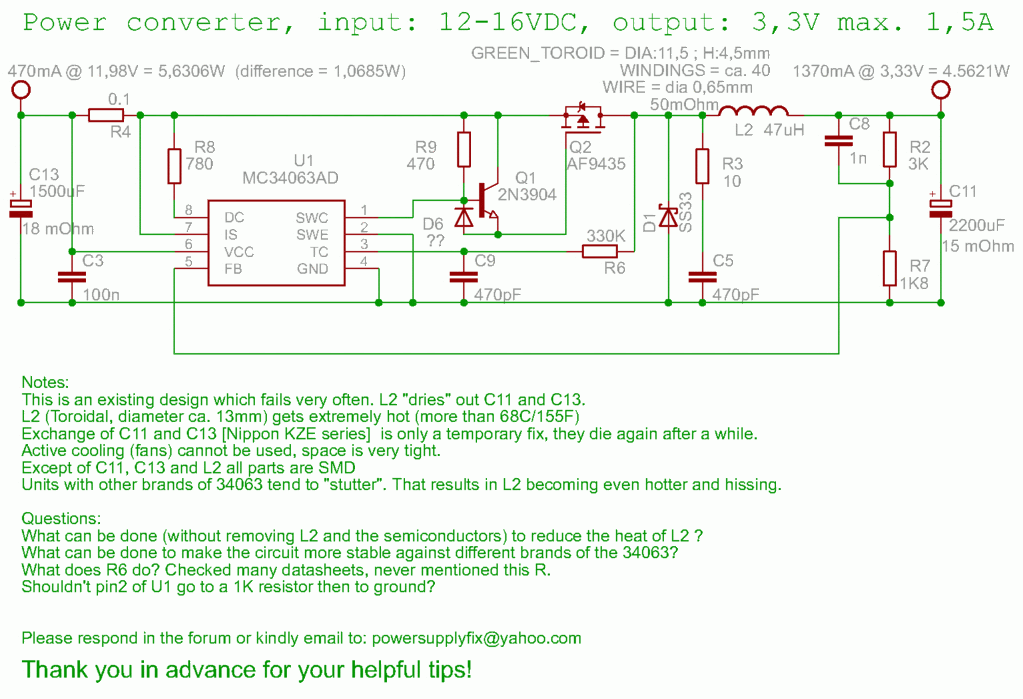
 
mc34063an schematic

The coil may have the saturation current too low. If this is the case, your only choices are to change the coil with one rated with higher Isat, or to reduce the consumption.
 
mc34063a coil

Hi, reducing consumption is not possible, but I might be able to add some coils to the existing, would that help?

Meanwhile I made the schematic, there are some more questions pelase:

What can be done to make the circuit more stable against different brands of the 34063?

What does R6 do? Checked many datasheets, never mentioned this R.

Shouldn't pin2 of U1 go to a 1K resistor then to ground?
 
mc34063a regulated power supply

I do not see the purpose of R6. If L2 saturates, I do not think there is anything to do besides changing it. Can you indicate the model of the coil? A datasheet for it will be helpful.

/pisoiu
 
Hi,
I made some measurements and updated the schematic.

The capacitors were EKZE250ETD types from United Chemi-Con and died after less than a year.

The toroid is in part covered by that nasty glue, so the windings are an interpolation of what I could count. Tried to be as exact as possible with the measurements.
The core is light green.
The laquer of the wire has turned light gold due to the heat.
New, never used units have that typical brownish color.

I measured the heat of the coil generated with the case closed, it goes close to 70C with 25C ambient.

And this mystery R6.
I waded through many application notes and scematics, but never encountered this. What could it achieve? They would not have put it in if they could have saved that part.


POWER7.gif
 
The q1/r9/d6 look a bit strange to me. I don't understand why the command is so complicated. I've attached a schematic with a similar PS I've used some time ago. The power consumption is not so big, around 2-300mA constantly, with spikes up to 2A (there is a GSM modem after). My opinion remains the same, I think the coil is saturating. Judging after the dimensions, my gut tells me that is too small, but not only the physical dimensions may indicate a problem. The ferrite core may be inappropriate for this application, and this can be seen only in the datasheet of the inductor. The ferrite core may have high losses. You can also check the ramp of the signal after R4, you should see something as a sawtooth there. A linear ramp would indicate correct operation. If ramp goes linear and after a time it rises exponentially, this is an indication of the saturation of the coil.
 
pisoiu, yes, you are right, the coil is way too weak.

I will try your suggestion with the ramps after R4 and put up the pictures, thank you!
 
The q1/r9/d6 look a bit strange to me. I don't understand why the command is so complicated.
It's a totem-pole driver and an intelligent way to drive a MOSFET fast from MC340634. Another question is, if the rather poor MC34063 PWM control
behaviour makes it a good candidate to build a high performance switcher. In my opinion, it's simply one of the cheapest available switcher chips.
So I agree that it's more appropriate to supplement it with simple BJT current boosters, if considered reasonable at all.

As one disadvantage, the inductor is reaching peak current under any load condition, so it's essential to keep clearly away from saturation point.

By the way, have you ever considered to utilize a ready to use National "Simple Switcher" or a similar low part count TI switcher solution?
 
I would love to replace the whole thing, but as mentioned, this is not possible.
This is an existing design deployed in may (poor) countries, and any fix must be done with minimal tools and efforts.
We can add parts on top of some of the parts, but removing them in general is not possible.

I found that I have access to the end of the coil where I can cut it open and insert more coils or so, but that's basically it.
Thankfully the capacitors are easily replaceable, seems the designers knew this is trouble.

That National switcher thing looks great, amazing what tools they've made.

I have added some more info in another thread.
If you could kindly have a look at them too, that would be great!

**broken link removed**
 
Hi

i think you use an MPP core first..about the winding u can reduce the lost too,if u use more Copperwire ..like 3 * 0.35Dia (Skin effect)
for what R6? and maybe u must remove C8 can be an oszilator with this...
And ur PCB design must be ok..Grounds only one point..and and..
C11 and C13 must be LOW ESR and 105 rubbycon ec....
Ur ciruit falls and high with the PCB Layout..

Willi
 
The said Nippon KZE is a good low ESR series and should work. R6 is dubious in fact, it's difficult to predict it's effect. MC34063 will never show stable PWM operation, either with or without C8, so you may want to check it's effect empirically.
 
On second thought, you can try another approach. If the coil core has high losses, you can try to lower the frequency. Put a higher C9. It's a long shot, but worth a try.
 
I added some more pictures in the above mentioned thread.

**broken link removed**

**broken link removed**

I did add 1nF and 2nF as you, pisoiu, and somebody in the other thread suggested. The cycles grew a little longer, but the weird pattern stayed.

FvM, I removed C8, it had no effect on the stutter.
I am not really after a totally syncronous or PWM operation, I just want those short spikes, which seem to heat up the core, be gone.

While playing around, I found that adding a 1.2nF capacitor between pin 3 and pin 7 of U1 makes the short spikes dissapear (and the pattern becomes quite synchronous).

And the heat goes down!.

But would that capacitor have a negative effect somwhere else????

What do you guys think?
 
The solution seems as mysterious as previously R6. Check if the circuit is operational under all input voltage and load conditions
and don't be too sure, that it still works with MC34063 exemplars from a different supplier...
 
FvM: I have been operating the unit with the 1.2nF "fix" (between pin 3 and pin 7 of U1) for nearly 24h, and all is well so far.
I will heat it up tomorrow and if it stays stable I'll do the addition to the "Quad "unit too.
The "quad" unit has a 4 stroke hickup and gets very hot.

There are some more interesting pictures of that "quad" unit showing the oscillator and the feedback pin, see link below please.

Any guess what mught be the reason for this strange behaviour?

**broken link removed**
 
R6 in your case will slightly stretch out the period.

Your current sense input affects the charge rate of the timing cap. Upon exceeding the 330mV, it hastens the charging of the cap, thereby reducing it's period.

Looking at some of your traces on the other site, specifically the ones that read across Rsc, you may notice the change of period following a hieghtened voltage that would be read by Ipk. I don't see a mention of scale, but is it possible that your Rsc is influencing Ipk. You indicate Rsc to be .1ohm. TI indicates this should be no smaller than .2ohm. What is your reading of this resistor?

If you are affecting Ipk, this likely would mean that your inductor is of too small a value. You may be able to offset this by taking your frequency up to the max of 100khz. I believe a 100pf timing cap should do this
 
GetDeviceInfo, you are very right, I took some pictures which I will attach here.
Some sweeps get wider with R6.
But it leaves still the question on why they did that.

Rsc is indeed 0,1 ohm, both on the package and measured at several units.

In the beginning, while searching for the reason of these strange patterns in some units, I had recalculated and found 0,1 Ohm to be in compliance with their formula of 0,3/Ipk(switch) .
Where from what I found Ipk(switch) is 2x the output current, so roughly 3A.

So 0,1 Ohm looked OK formulawise.

I like the idea of rising the frequency. In one of the experiments Ct was disconnected accidentally and the thing was swinging in the upper several hundret KHz. No squeeching noise and it was suprisingly not as hot as with the regular schematic.
But others warned me of eddy currents and other things I don't understand, to not go higher, but lower the frequency.
What do you think about their warnings?

From what I have learned so far, it seems that an overcurrent occurs which resets a cycle or so. Would that explain the weird quad pattern in those last graphs?
But why only on that unit, and others have a double or triple pattern, why?

These are the pictures of the same quad unit as pictured in the above link.
These are with the strange R6 in place, showing the stretched ramps as you said:

The first pic is always the main shot followed by zooms.

Timing is 50uS, top curve is Pin 3 (TC) which starts somewhere from 130mV up to 1,4V (the last and highest peak before a longer down ramp starts).

Bottom is junction of R3 and L2.
The "zoom ins" are a 10x magnification of an area from the main, normally in continuation, 5usec per div.

CIMG9666s_quad_50us_yesR6.jpg


CIMG9667s_quad_5us_yesR6-a.jpg


CIMG9668s_quad_5us_yesR6-b.jpg


CIMG9669s_quad_5us_yesR6-c.jpg


CIMG9670s_quad_5us_yesR6-d.jpg


Added after 5 minutes:

And here are the pictures with R6 removed.

The quad pattern, noise and heat all remain, nothing changes in that regard.
The first pic is always the main shot, followed by zooms.

Timing is 50uS, top curve is Pin 3 (TC) which starts somewhere from 130mV up to 1,4V (the last and highest peak before a longer down ramp starts).

Bottom is junction of R3 and L2.
The "zoom ins" are a 10x magnification of an area of intrest from the main, normally in continuation, 5usec per div.

CIMG9662s_quad_50us_noR6.jpg


CIMG9663s_quad_5us_noR6-a.jpg


CIMG9664s_quad_5us_noR6-b.jpg


CIMG9665s_quad_5us_noR6-c.jpg


Added after 2 hours 16 minutes:

I tired the 100pF menawhile.
The pulses are shorter but the general pattern of very short bursts (now up to 10) with periods of "silence" remain the same.
And the squeeching and heat is also the same.

I am quite sure that this fast succession of these short pulses are too much for the coil, I just don't know how to prevent them from happening (except the 1.2nF thing mentioned earlier).

I added 100nF directly to the power pins of U1, just in case, no change.
 
Just a suggestion. Use a graphics program (e.g. Irfanview) to annotate the screenshoots. Add node names to the
individual traces and time and voltage scales, and possibly a short description of varied parameters. Otherwise, it's rather
annoying to decode the various pictures. Im sure, I'm not the only one...

Sometimes, I get mysterious diagrams or screenshots from customers, too. But they mostly have DSOs providing some basic information.
And I'm paid for the puzzling work.
 
Thanks for the suggestion.

Knowing how busy you all are I try to make it as easy as I can.
That's why I read the FAQ's and guidelines and prepared the schematic etc.

Just downloaded that program and am getting acquainted with it.

Will use it for future pictures to amend the text into them.
 
increasing your switching frequency may increase switch losses, so there are tradeoffs.

Going back to your original situation, is there a concern with a number of these devices, indicating a design problem, or is the problem isolated to a few of them, which may indicate component degredation.

seeing that you have a torodial, it may be worthwhile in wrapping a current sense winding so that you can view the coil current.
 
Status
Not open for further replies.

Similar threads

Part and Inventory Search

Welcome to EDABoard.com

Sponsor

Back
Top