Continue to Site

Welcome to EDAboard.com

Welcome to our site! EDAboard.com is an international Electronics Discussion Forum focused on EDA software, circuits, schematics, books, theory, papers, asic, pld, 8051, DSP, Network, RF, Analog Design, PCB, Service Manuals... and a whole lot more! To participate you need to register. Registration is free. Click here to register now.

Help with Lin to Exp/Anti-Log converter as current source

Status
Not open for further replies.

juz_ad

Full Member level 2
Joined
Dec 17, 2011
Messages
130
Helped
0
Reputation
0
Reaction score
0
Trophy points
1,296
Activity points
2,541


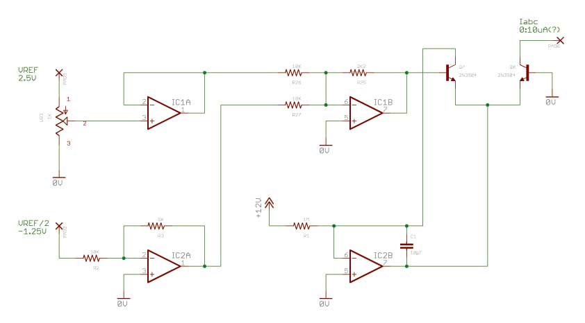
I'm trying to set up a Linear to Exponential/Antilog current source to drive a transistor differential amp (that has a linear response).

Using a Linear current mirror with an input voltage of 0 to 2.5V, converted to approx. 0 to 10uA I get a nice straight linear response and unity gain at the output of the differential amp from 0 V PP to approx. 10 V PP - so I know the differential amp is working as required.

I would like to take the same control voltage of 0 to 2.5V, convert it to approx. 0 - 10uA (although I can be flexible about that...) and convert the output curve (Iabc) to an exponential response.

So far, the schematic above, made up from my own research and data sheets is not giving me the required response and adjusting the various resistor values just seems to be shifting the linearity/gain response upward/downward and not bringing me any closer to an exponential/antilog curve.

Can anyone offer any advice on component values I should be looking at, things I could check/change, what I might be doing wrong?

Thanks in advance.
 

I don't understand what you mean with linear response of the differential pair. For the output current, you can expect

Iabc = 12 uA * exp(-ΔUb/26 mV)

which isn't linear. The ΔUb range of the present circuit isn't quite clear. Is the input voltage of the inverting OP stage -1.25, as written in the schematic, or +2.5 V, which seems more suitable.
 

I don't understand what you mean with linear response of the differential pair. For the output current, you can expect

Sorry - I might have made this confusing. The current source in the schematic above is driving a separate differential/long-tail pair (running off Iabc). When I use a linear current source to drive that separate long tail-pair - I get a linear output from the current source and at the output of the long-tail pair.

My aim is to use the antilog source in the schematic above to get an antilog/exponential output. Does that make more sense?

Iabc = 12 uA * exp(-ΔUb/26 mV) which isn't linear.

Is that the equation for the output current (Iabc) of the schematic above? Then - no - it shouldn't be linear, it should be antilog... but my problem is that so far, on the breadboard - it isn't.

Please excuse my maths - but can you point my to a reference that would explain what -ΔUb represented?

Is the input voltage of the inverting OP stage -1.25, as written in the schematic, or +2.5 V, which seems more suitable.

The input control voltage is from 0 to +2.5V (when driving the separate long-tail pair to control gain this gives an output of between 0 and 10V PP (+/-5V) from a 10V PP input. The -1.25V input was necessary to bias the +2.5V CV and get the long-tail output to go down to 0V - otherwise the output of the long-tail pair was between approx. 2V PP and 10V PP.

I admit this does appear to be a problem and other antilog schematics I've seen don't appear to need any biasing. It did fix one problem, not sure if it hasn't caused other problems.

Thanks again for your input - I hope these explanations make my problem a bit clearer.
 

I can only refer to the circuit as it's shown in post #1. Iabc can be measured e.g. with a shunt resistor, or an OP I/V converter, you don't need additional transistors for the basic circuit function. Biasing of the transistor pair should be primarly discussed related to the intended Iabc current range, I think.

ΔUb in the expression means the difference of base voltages, or in other words the output voltage of IC1B.
 

Status
Not open for further replies.

Part and Inventory Search

Welcome to EDABoard.com

Sponsor

Back
Top