codename25
Member level 3
HI all,
I'm planning to build an LED message board with 8X64 led. I'm planning it to do with ATmega16 (Since i have one with me). I'm a beginner in both micro-controller and C program. So, I need all of your generous and valuable help, also this might be helpful for others who are in same situation.
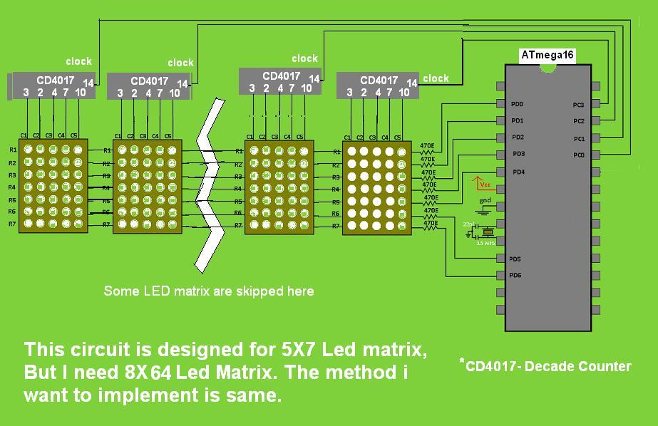
I'll explain my current situation. I want to do the whole 8X64 led project by one Atmega16. Since, It has only 4 ports with 8 pins each. It's impossible to connect all these 64 column pins with the micro-controller ( From four i need one whole port for row execution). So, i decided to use decade counters(CD 4017), each CD 4017 gives me 8 pins of output (to columns) by only giving an input clock from the micro-controller. If you see the circuit & program you can easily understand what i mean. Now my problem is:
1) I don't know whether the program is correct or not (or even don't know whether it works well as expected).
2) I don't know whether the circuit is correct or not.
3) What all should i include or modify my program to make the message in the display scroll.
I haven't started the hardware section of the project till now. since, it needs lot of LEDs and effort, I just thought of starting it only if the circuit and the program works theoretically well.
Now, I need the help from you people to solve this issue and help me to complete and succeed in this project.
Thank You.
Code and circuit diagram are displayed below:

I'm planning to build an LED message board with 8X64 led. I'm planning it to do with ATmega16 (Since i have one with me). I'm a beginner in both micro-controller and C program. So, I need all of your generous and valuable help, also this might be helpful for others who are in same situation.
I'll explain my current situation. I want to do the whole 8X64 led project by one Atmega16. Since, It has only 4 ports with 8 pins each. It's impossible to connect all these 64 column pins with the micro-controller ( From four i need one whole port for row execution). So, i decided to use decade counters(CD 4017), each CD 4017 gives me 8 pins of output (to columns) by only giving an input clock from the micro-controller. If you see the circuit & program you can easily understand what i mean. Now my problem is:
1) I don't know whether the program is correct or not (or even don't know whether it works well as expected).
2) I don't know whether the circuit is correct or not.
3) What all should i include or modify my program to make the message in the display scroll.
I haven't started the hardware section of the project till now. since, it needs lot of LEDs and effort, I just thought of starting it only if the circuit and the program works theoretically well.
Now, I need the help from you people to solve this issue and help me to complete and succeed in this project.
Thank You.
Code and circuit diagram are displayed below:
Code:
#define <avr/io.h>
#include<util/delay.h>
unsigned char seq[]={
0b01111111,
0b00001001,
0b00001001,
0b00001001,
0b00000110,
};
int main()
{
DDRC=0xFF;
DDRD=0xFF;
PORTC=0;
PORTD=0;
int i=0;
while(1)
{
for(i=0;i<8;i++)
{
PORTC=(1<<PC0); // or PORTC=0X01
_delay_ms(1); // clock of 1ms delay pulse to CD 4017
PORTD=~seq[i]; // row execution according to the char seq [] given above
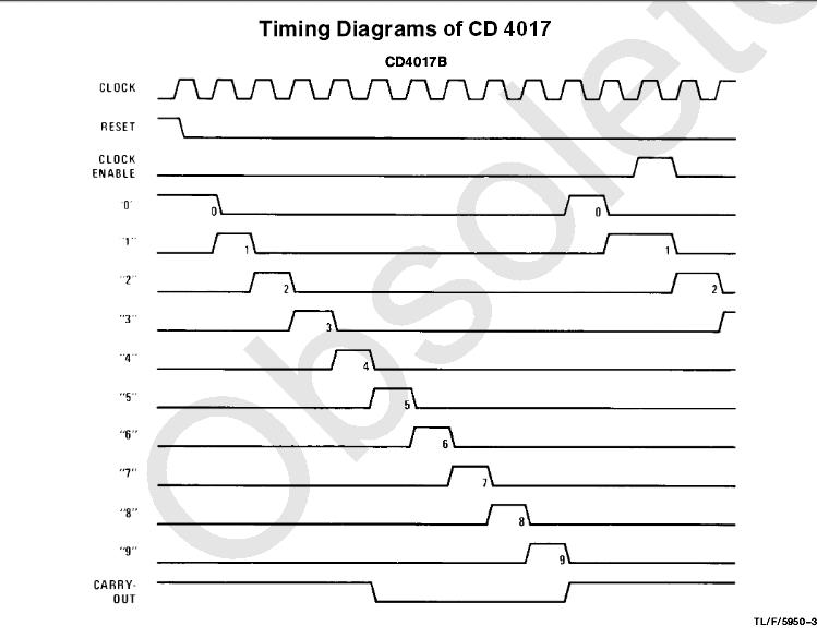
_delay_ms(2); // CD 4017 O/P pins delay is double the input pulse (according to its datasheet)
}
for(i=0;i<8;i++)
{
PORTC=(1<<PC1); // or PORTC=0X03
_delay_ms(1); // clock of 1ms delay pulse to CD 4017
PORTD=~seq[i]; // row execution according to the char seq [] given above
_delay_ms(2); // CD 4017 O/P pins delay is double the input pulse (according to its datasheet)
}
for(i=0;i<8;i++)
{
PORTC=(1<<PC2); // or PORTC=0X07
_delay_ms(1); // clock of 1ms delay pulse to CD 4017
PORTD=~seq[i]; // row execution according to the char seq [] given above
_delay_ms(2); // CD 4017 O/P pins delay is double the input pulse (according to its datasheet)
}
for(i=0;i<8;i++)
{
PORTC=(1<<PC2); // or PORTC=0X0F
_delay_ms(1); // clock of 1ms delay pulse to CD 4017
PORTD=~seq[i]; // row execution according to the char seq [] given above
_delay_ms(2); // CD 4017 O/P pins delay is double the input pulse (according to its timing diagram)
}
}
return 0;
}