jogzzz
Newbie
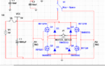
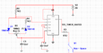
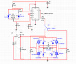
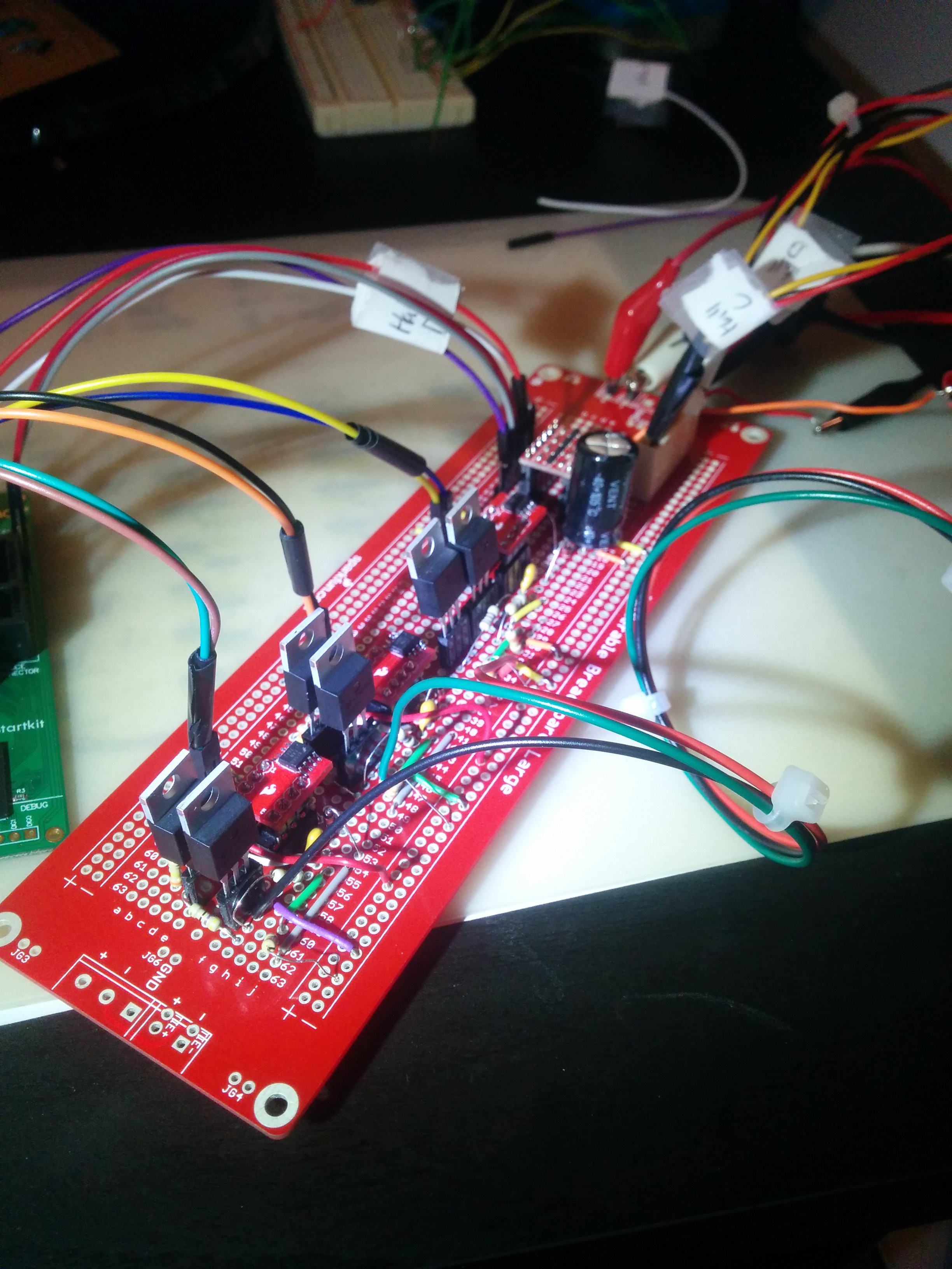
i am a 2nd year electronic engineering student. my task was to design an H bridge circuit to control the speed and direction of a DC motor that is rated at 2A, 5V using MOSFETS and any simple circuit for PWM (to control the speed) on multisim. I chose to use a simple 555 timer PWM circuit and designed the h bridge as in the attached file. both circuits ( the h bridge and the PWM circuit) function correctly on their own. I simulated the H bridge using a function generator and it worked perfectly but when i added in my own PWM I keep getting simulation errors. please help lead me in the right direction. I don't have access to lab technicians or lecturers to help due to the corona virus lockdown and i am desperately trying to figure out what to do to make this circuit work with my very limited knowledge. thanks in advance for any help whatsoever.