Continue to Site

Welcome to EDAboard.com

Welcome to our site! EDAboard.com is an international Electronics Discussion Forum focused on EDA software, circuits, schematics, books, theory, papers, asic, pld, 8051, DSP, Network, RF, Analog Design, PCB, Service Manuals... and a whole lot more! To participate you need to register. Registration is free. Click here to register now.

HELP with diff amp circuit design

Status
Not open for further replies.

gareth-71

Newbie level 5
Newbie level 5
Joined
Aug 3, 2010
Messages
8
Helped
1
Reputation
2
Reaction score
1
Trophy points
1,283
Location
UK
Visit site
Activity points
1,338
Hi

I need help with a relatively simple Analog design problem....

I have a differential signal that I am 'tapping' into. (It goes to another system...so input impedance of my circuit must be high > 100kR).

The characteristics of the signal are:

Amplitude can be 1vpp to 5vpp
Offset is always positive (and the signal never goes negative) and can be from 0 to about 5v
The signal can be sine or square wave and neither of the two signal wires are ground biased.

Output requirements are simply ground referenced signal, preferably square wave.

I thought of using a simple diff amp, and in simulator it works, but in practice not at all.
 

Hi

No, I don't. My attempts are not working, so I thought I would see what ideas came up and then design around that to see what people think.
 

Ok, so I think what I am trying to do should be simple enough with a diff amp...

The signal is not ground biased, so I need to convert it being ground biased.

How do I convert a non-ground biased signal to a ground biased signal?

One way I guess I can do it is by using an ADC with differential inputs and then use a micro to measure the difference in values and process from there, but this sounds like a very difficult way of doing it.
I have tried using diff amps in the simulator and then in practice and I do not get the same output in practice, in fact the output is nothing like expected.

I have not designed with OpAmps or any kind of diff amps, rather I usually do rudimentary signal conditioning and then process in a micro.
As this signal is not Ground biased, I am stuck....
 

Please notice that "diff amp" isn't a particularly clear specification. But yes, the problem can be perfectly solved with some kind of differential amplifier.

How do I convert a non-ground biased signal to a ground biased signal?
Using a differential amp with sufficient common mode range.

Is it asking too much if we want to understand what you exactly did? As we don't know what the problem is, do you expect us to retell a text book about amplifier circuits?
 

The easy way is to AC couple the signal and clamp "your" side with a diode to earth (cathode to earth), now you know that the negative side of your waveform, will be at -.7V, so if you operate an open loop opamp withVref = .7V, it should work .
Frank
 

Hi

I can't interfere with the signal. So diodes / clamps etc are a no no unless I can use 100kR resistors in series with the two input lines...


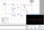
Here is a signal conditioning circuit that works on the sim but not in practice.
Interestingly I accidentally swapped the inputs on the last OpAmp and it works great....on the Sim.
Also, if I try and use LM324 in sim, it does not work...????

Sim1.jpg
 

I tried to post image, but I have a message saying Admin needs to approve...

- - - Updated - - -

Please notice that "diff amp" isn't a particularly clear specification. But yes, the problem can be perfectly solved with some kind of differential amplifier.


Using a differential amp with sufficient common mode range.

Is it asking too much if we want to understand what you exactly did? As we don't know what the problem is, do you expect us to retell a text book about amplifier circuits?

No, not at all. I am interfacing to ABS signals on a race car. Normally I can interface directly and this works great (because I can bias the signal directly to Gnd), but in this application there is a traction control device that uses these signals, and it, for one reason or another, puts a DC bias on.
 

The preferred way to probe the signals without loading it is to use an amplifier with a common mode range above the DC bias level, similar to the instrumentation amplifier in post #8. This works with standard OPs up to a few 10 V and respective high supply voltage.

Another option is to use differential voltage dividers in front of the differential amplifier. Industry standard differential probes for oscilloscopes are working this way and can handle up to 1000 or 2000 V common mode voltage with a moderate input impedance of e.g. 10 MOhm.
 
You can't amplify a signal with a 5V DC offset using a 5V supply. You should go to at least 10V for the supply and use a higher voltage op amp.

Using an instrumentation type differential amplifier IC would give better performance with fewer parts.
 
The requested >100 kOhm input impedance isn't particularly difficult to achieve. What's the required signal speed? Do you expect high frequent common mode nose? A differential amplifier with voltage divider may be sufficient.

See TI INA117 as a commercial IC using this technique.
 

Status
Not open for further replies.

Similar threads

Part and Inventory Search

Welcome to EDABoard.com

Sponsor

Back
Top