Continue to Site

Welcome to EDAboard.com

Welcome to our site! EDAboard.com is an international Electronics Discussion Forum focused on EDA software, circuits, schematics, books, theory, papers, asic, pld, 8051, DSP, Network, RF, Analog Design, PCB, Service Manuals... and a whole lot more! To participate you need to register. Registration is free. Click here to register now.

Help with current sensing circuit.

Status
Not open for further replies.

Al J

Newbie level 5
Joined
Jul 28, 2011
Messages
9
Helped
0
Reputation
0
Reaction score
0
Trophy points
1,281
Activity points
1,360
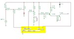
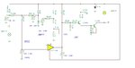
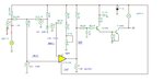
Having trouble with a current sensing circuit used to detect if a break light is out (automotive.) The attached is what I managed to trace from the card.

SCAN0285.JPG

The highlighted chip is a 5 pin op-amp that I cant cross reference. I am not certain of the polarity of either of the transistors, nor of which pin is base and which is collector on the highlighted transistor. Help would be appreciated!
1) probable polarity of the two transistors
2) which pin is B and which is C on highlighted transistor
3) probable pin out of the op-amp.
4) how the heck this thing works.

Thanks for any help you can give.
 

Maybe this is the correct schematics, but some resistors values are not so important now.
The circuit compare voltage on pins ‘’REF’’ and ‘’INPUT’’, any change in the light consumption may affect the voltage on the resistor R11, also the voltage on the ‘’INPUT’’. This will trigger an output command.
 

Attachments

  • Light circuit.JPG
    Light circuit.JPG
    64.6 KB · Views: 76

check circuit. connection of "C" ("B"?) lead should have been to junction point of R10/C1/R9 and not on the other side of R10. That side of R10 simply goes to gnd. If it helps any, the op amp pins are numbers backwards. Still have no clue as to what the op amp pins are (vcc, +, -, out).

---------- Post added at 22:06 ---------- Previous post was at 21:38 ----------

OP amp
1 : gnd
2 : +
3 : out
4 : -
5 : vcc
I hope. And no matter what my ohm meter says the out put transistor has to be a NPN.

---------- Post added at 22:07 ---------- Previous post was at 22:06 ----------

M_RF: your thumbnail didn't show up until after I posted the above. looking at now.
 

Maybe in circuit it's a simple low power voltage comparator. See how the circuits react to lights ON and OFF.
 

Attachments

  • Light off.JPG
    Light off.JPG
    82.1 KB · Views: 68
  • light test on.JPG
    light test on.JPG
    80.4 KB · Views: 73

Status
Not open for further replies.

Part and Inventory Search

Welcome to EDABoard.com

Sponsor

Back
Top