Continue to Site

Welcome to EDAboard.com

Welcome to our site! EDAboard.com is an international Electronics Discussion Forum focused on EDA software, circuits, schematics, books, theory, papers, asic, pld, 8051, DSP, Network, RF, Analog Design, PCB, Service Manuals... and a whole lot more! To participate you need to register. Registration is free. Click here to register now.

Help with boost converter

Status
Not open for further replies.

nafnaf

Junior Member level 1
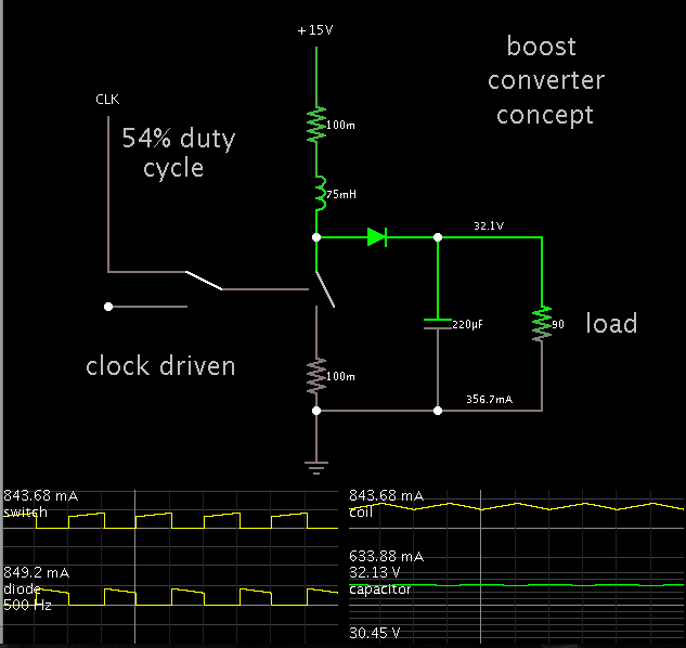
Joined
Aug 21, 2012
Messages
16
Helped
0
Reputation
0
Reaction score
0
Trophy points
1,281
Activity points
1,388
Vin 15v
Vout 30v
Pccm 10w
f=500hz

i just add a 2n222 that i see from web .what is the function of this 2n222 111.JPG

is the inductor current right like this 22222222222.JPG

any opinion on my ckt
 
Last edited:

Hi, is it boost converter?

Vin=15v and Vout=13v

Are you sure?

By the way,
i just add a 2n222 that i see from web .what is the function of this 2n222
I think R2 is the biasing resistor acting for 2N2222.
When C2 charges upto the voltage sufficient to turn on the 2N2222 then it will set the ref voltages.
In simple words, 2N2222 is acting as a switch here just.

is the inductor current right like this
Yes, it is the inductor current like this. Actually, you know that inductor first try to oppose its change then gets stable.

NOTE:
May be I wrong. But I just tried to help you friend.

Princess
 

It's a boost converter, and the configured output voltage is not 13 V (actually about 27.5 V)

The external transistor is for slope compensation, unfortunately not explained in the datasheet.
 

its 30v

why it needs a switch in r1/c1 and why the emitter is connected in isense
i tried without the 2n222

with 2n222

with_2n2222.JPG

without 2n222wouth_2n222.JPG
 

The transistor isn't working as a switch. Just google for "slope compensation".

You have verified, that the instable behaviour hasn't to do with missing slope compensation. I guess it's a problem of unsuitable feedback compensation. If you want others to check your setup, you'll post the *.asc file.
 

Not idea what you mean with "not aligned"? rt/ct sets the frequency of operation.
 

RT/CT is the internal oscillator terminal, always give a triangular wave. It will be use full for slop compensation. How it will align to output voltage?
It will take some fraction of second for stabilizing the output voltage in each DC to DC converter.DCTODC.png
 

I am running a simulation of a simple boost converter with your specs.
Coil 75mH.
500 Hz operation.

Here is a screenshot, with scope traces.


Coil waveform should rise to about 900 mA during each cycle, then decline to a fraction of that.

Yours reaches that Ampere level, but then rapid parasitic oscillations set in during the uppermost part of the waveform. These oscillations prevent proper operation of your converter, and they must be suppressed somehow.

Also notice that your smoothing capacitor need not be so large a value. A few hundred uF will be enough to smooth the output ripple to 1 or 2 V.
 

Not idea what you mean with "not aligned"? rt/ct sets the frequency of operation.

i think the the pin 4 (RT/CT) and pin 6 (OUTPUT of lt1243) should be like this like this.JPG in simetrix

but i see in the ltspice is not aligned like this
nnnnnnnnnnnnn.JPG
 

No. In current mode, the on-time is ended by the current comparator. Please review the block diagram in data sheet, particularly pay attention to the RS flip-flop.
 

What is the advantage for 500Hz operation?

Disadvantages for 500Hz (Low frequency) operation.
1) Inductor size will be huge.
2) Capacitor size will be huge.
3) LT1243 are not recommended for low frequency operation.
4) Noise filtering is not easy for low frequency operation.

Try R2 - 1.5K and C2 - 10nF, Frequency will be 80KHz and duty cycle will be 68% .Slope compensation design accordingly.
 

Disadvantages for 500Hz (Low frequency) operation
I agree every point, except for 3. There's no lower switching frequency limit stated in the datasheet. Why should it?

None of the problems/questions adressed by the OP is related to low switching frequency.
 

the power in in 1 ohm resistor reaches 56w 1ohm.JPG
should i use a 60w resistor is this possible ?
i only see 1w to 10w resistors in some stores here

here is the new cktView attachment www.zip
 

Yes. Data sheet not showing the minimum operating frequency. But it should be a minimum operating range for decried performance.
 

Status
Not open for further replies.

Similar threads

Part and Inventory Search

Welcome to EDABoard.com

Sponsor

Back
Top