Continue to Site

Welcome to EDAboard.com

Welcome to our site! EDAboard.com is an international Electronics Discussion Forum focused on EDA software, circuits, schematics, books, theory, papers, asic, pld, 8051, DSP, Network, RF, Analog Design, PCB, Service Manuals... and a whole lot more! To participate you need to register. Registration is free. Click here to register now.

Help with 7 segment LED

Status
Not open for further replies.

Snake126

Newbie level 6
Joined
Dec 16, 2010
Messages
12
Helped
1
Reputation
2
Reaction score
1
Trophy points
1,283
Activity points
1,361
Hello everyone, I am working on a project where I would like to install one of these:
**broken link removed**

and have it display completely random things (dont even have to be numbers) How could I possible go about doing this?

Thanks
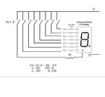
 

Here is most simple schema how to add switches to 7-segment.

7-segm.schema.jpg

or should it be more complicated ?
 
Last edited:

Your schematic is correct, provided you identify the pins correctly, one segment or the decimal point should operate with each switch.

Brian.
 

Ideally I would like to have the single 7 segment, and one switch to turn it on. And while it is on, it is displaying completely at random.
 

To do that requires some computing power. what you are asking for is a single 'enable' signal to turn it on and a random pattern generator to select which segments are powered. It's easy to do but you will need either a microprocessor or several logic gates. If you use something like a PIC 16F628A which is very inexpensive, you can do it all in one chip and the code would be very simple.

Brian.
 

The more I think about it, it doesnt even have to change randomly. Is there a way to just be able to flip a switch, the display powers up and have it wired to show something that isnt a letter or number? something that could be percieved as "alien" is what I am getting at.

If you could show me how to do this or point me in the right direction it would be awesome

Thanks for all your help
 
Last edited:

You can easily hard wire the display for a particular pattern. If you want something really alien looking like was used in the movie "Predator", use a 14-segment display such as these: LED Display's (scroll down a bit). Just be sure to use a dropping resistor for each segment to keep the current between 15-20 mA (the resistor value will vary depending on your supply voltage).

If you wired all segments through a set of dip switches you could change the design at will between uses.
 

That is exactly what i was looking for. Thanks! How would I go about figuring out what pins do what? Take the leads from a 9v battery with resistors on them, and start touching them to see?

Thanks again

Also, that multi-color bargraph one looks like it would work well too. (making a control panel/pad) Do those have a unique way of being wired up?
 

Yes, a battery with two leads with a 470Ω or higher resistor on one lead will allow you to map the pinout of a device if you don't have the data sheet, but they're usually available.

Most bar graph displays have individual LEDs without a common connection.

I'm assuming this is all intended for a special effect type display rather than some measurement function.
 
So, for the red bargraph. LED's/LCD's - LED Display - LEDBARRED The first light would light up if I touched the leads on pins 1 and 20? Does it matter which is positive/negative? How would I go about having them all lit up?

Sorry for all the questions Kj6EAD, but you have no idea how much you are helping me out with this. After these questions, I think I will understand.
 

The more I think about it, it doesnt even have to change randomly. Is there a way to just be able to flip a switch, the display powers up and have it wired to show something that isnt a letter or number? something that could be percieved as "alien" is what I am getting at.

If you could show me how to do this or point me in the right direction it would be awesome

Thanks for all your help

If you just wanted to show some random segments turning on and off, you could use a shift register IC, like the 74HC164, and a 555 timer to clock it.

Here's the setup I could see.

1. Connect the 8 output pins of the shift-reg to 8 input pins on your 7-segment display (7 segments + decimal point, if you have it). You might need to run the IC outputs to 8 small BJTs/FETs, if the shift register can't source enough current to turn on the LEDs (check the datasheet).

2. Connect the Clear pin to +5VDC, using a 1k or 10k pull-up resistor (it's inverted internally, so we need to give it a logic "0" from the outside world).

3. Connect one of the shift-register outputs (probably D,E,F or G) to the serial input pins (yes, both... they are run into a NAND gate internally). This will make the sequence come out in a pseudo-random pattern.

4. Set up the 555 timer as an Astable Multivibrator. This will go to the clock (CLK) input on the shift-register (set it up for about 500-1000 ms period... 0.5 - 1 second delay between "characters").

Use your "one switch", to turn on a +5V supply to the chips, and viola! Also, you might need to use an LM7805 (or similar) linear regulator to take 6V or 12V down to the +5V you'd need.
 

Polarity matters and is marked positive(+) for the anode and negative(-) for the cathode end in the schematic. For diodes, including LEDs the bar end of the symbol that the triangle points to is the cathode. By the way, a 9-Volt battery will not supply enough current for very many segments for very long. A plastic battery holder with 4-8 AA cells might be a better choice.

There are lots of tutorials on line that can show you how to power LEDs from batteries. These multi-segment displays are the same except that they share a pin for the cathode or anode connection to reduce the number of pins on the device.
 
Last edited:
So how would I go about making all of them light up at once? Run the appropriate + and - wires to each pair of pins, and treat them as seperate LEDs independent from the rest, and give them their own resistors?
 

See above. It's very important that each LED have it's own resistor. At the risk of confusing you, I'll mention resistor packs (SIP or DIP) that can save some space if you need a lot of resistors of the same value.
 
See above. It's very important that each LED have it's own resistor. At the risk of confusing you, I'll mention resistor packs (SIP or DIP) that can save some space if you need a lot of resistors of the same value.

Thanks for all your help!
 

This would be simple to do with a microcontroller, if one is set up to use microcontrollers, of course.

Two other ideas come to mind:

1) Use a 555 timer clocking a 7490 decade counter, feeding a 7447 7-segment driver, which controls your display. Instead of hooking up the display segments correctly, hook them up at random. Google "+7447 +7490" for lots of examples of this simple counter circuit.

2) Use a 74C926 to replace the 7447 and 7490. You'll still need the clock (555 timer), but this will let you control multiple 7-segment displays with this one IC.


**broken link removed**
 

Status
Not open for further replies.

Part and Inventory Search

Welcome to EDABoard.com

Sponsor

Back
Top