Continue to Site

Welcome to EDAboard.com

Welcome to our site! EDAboard.com is an international Electronics Discussion Forum focused on EDA software, circuits, schematics, books, theory, papers, asic, pld, 8051, DSP, Network, RF, Analog Design, PCB, Service Manuals... and a whole lot more! To participate you need to register. Registration is free. Click here to register now.

Help with 24 led light powered by 12 Volt car battery

Status
Not open for further replies.

campus189

Member level 5
Joined
May 7, 2011
Messages
84
Helped
0
Reputation
0
Reaction score
0
Trophy points
1,286
Location
Tennessee,USA
Activity points
1,940
**broken link removed**


Hopefully someone can help me here..
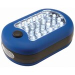
I want to run this 24 led light on a 12 volt car battery. This will be for when the power goes out.
I want to run about 4 of these if I can in my house with the battery being charged by a 4 watt solar battery charger in the day.
It takes 3 AAA Batteries & draws about 480mA , a little less than ½ an amp. And has a voltage reading of 4.7 Volts
I tried using LM317 & 7805 on a bread board, they both heat up a lot.
Without the led light hooked up, I used a potentiometer and got the voltage to a perfect 4.5 volts DC
When I connect the led light it dims big time and the heat sink heats up big time.
I got a feeling that the resistor values may be wrong.
I tried to use the LM317 resistor calculator, but am still having problems..
Any idea what I am doing wrong? I don’t want to spend tons of money trying to figure this out.
If someone could give me some idea as to what to use for resistors or something else, it would be greatly appreciated..

Thank You
 

Attachments

  • image_4737.jpg
    image_4737.jpg
    24.7 KB · Views: 150
Last edited:

With bright white LED's at 3.6 V each, and a 12 or 13 V battery, you can build strings of 3 led's maximum.

Each and every string must have its own current limiting resistor, around 150 ohms. This limits current to 17 mA through each string.

A 120 ohm resistor allows 21 mA to flow. It may be okay to use. I'm not sure I want to fry $9 worth of led's.

You can power as many strings in parallel as you wish. If you have 5 strings then you need 5 current limiting resistors.

You cannot get away with using a single current limiting resistor. One led string may hog all the current from the other strings.

This is to say, you need simple current limiting. It's too difficult to regulate voltage alone to stay within the tight operating range that works with PN devices (such as led's).

I believe there's a way to configure a voltage regulator to operate as a current limiter. But a voltage regulator IC is more than you need.

================================

I made a bright white LED to come on automatically when a blackout happens.

It's controlled by a relay whose contacts stay open all the time I have house current.

The led is powered by 3 half-used D batteries. Seems there's always a surplus of half-used batteries.

Lasts days.

More portable than if it were powered by a car battery.

---------- Post added at 18:44 ---------- Previous post was at 18:40 ----------

-----------------

Excuse me, now I see you mentioned AAA battery power. Are you making portable LED flashlights that run on 3 AAA's ?

---------- Post added at 18:48 ---------- Previous post was at 18:44 ----------

And yes, a small device will heat up when drawing 480mA with 4.7 V across it. That makes over 2 watts. Burns the fingers.
 
Last edited:
Thank you so much for the reply.
No, I'm not making portable led flashlight.
These will be mounted on the wall permanently.
Look as the attachment up above to see light that i am trying to power :)
Our power goes out a lot here in Tennessee and for 3-5 days at a time :(
I want to use the light in the attachment above in the house for light when the power goes out.
I'm hoping to use about 4 of these, each with it's own resistor or LM317/7805 connected to car battery. It's just hard to figure out the correct resistor value for just one light.
If I can get one to work, I would just duplicate the process for the other 3
It would be nice if the voltage drops below a certain point that the led's just dim or don't work.
Being as I only want to run 4 of these, it should only be a 2 amp draw on the battery total.
I have been pulling my hair out trying to figure this out :-(
I knew all this in school, but that was a long time ago,lol
Thank You for the reply
 
Last edited:

Go to the local thrift store and buy some surplus car cell phone chargers that have an output voltage of 4.5V-5.0V and at least 500mA of current capability. These are efficient switch mode voltage regulators, not heaters such as the linear regulators you've been considering. The extra half Volt won't hurt anything...probably. This assumes that the unit has a microcontroller (multiple modes would be controlled by one button).

On the other hand, if you look inside and find that all the LEDs are wired in parallel with no dropping resistors and the switch clicks when you push it, you can add 100Ω to each LED to make the LEDs run on a 5V supply. Use whatever resistance value gets each LED to 20mA.

For connectors, you can either make or buy some dummy AAA cells or use small alligator clips.

An alternative more reliable source but also a more expensive option would be something like this: Walmart.com: Scosche Dual USB Car Charger: Auto Electronics.
 
Last edited:
Yes, that is best... a DC to DC converter which you hook up to 12V and it puts out 4.5 or 5v without wasting hardly any power.

So now I get it... the flashlight is made to run normally on 4.5 V. This is why your regulators overheated by dropping 12V to 4.5 at half an amp. Many watts wasted.

So the LED's seem to be matched within a few hundredths of a volt. In that case a single dropping resistor will be sufficient, if you want to reduce current from the DC converter.

Overcurrent reduces an led's useful life. What's too much? Hard to be sure anymore because over the years bright white led's have been made with various ratings.

Twelve years ago I made several portable flashlights using a bright white led. Mail order from an electronics supply. Before LED flashlights were commercially available.

When one led cost $4 each.

Rated 3.6V. I used 3 half-used AA cells. 1.15 to 1.3 V per cell.

I put them in a compact battery holder for 4 AA cells. Soldered the led to the battery springs in the empty compartment.

The switch is the top terminal plate from a 9V battery.

Easy to make. Minimal expense.

I thought of making a stationary lamp with more led's, powered from my 12V battery.

For mealtimes, keeping warm around the woodstove, etc. (To take the place of the propane lantern in case Y2K caused social breakdown.)

However I figured such a lamp would be superfluous since we would have light from several portables. Because every member of the family would need to carry a portable LED flashlight constantly in a blackout.

I also knew battery V could be as high as 14.5 after charging, and drop to 12.5 after using it a few hours. A resistor would protect the led's at the higher voltage. But at lower voltage the same resistance would cut down current unnecessarily.

I decided that using led light simply and efficiently would be work. So I didn't make a stationary LED lamp.

No biggie. Y2K did not result in the breakdown of the electric power grid.
 
Last edited:
**broken link removed**
There are 2 resistors.
The small one (Tan), I believe is for the switch, having color bands of Grey-Red-Gold-Gold
The Large one (Blue), Is either Violet-Green-Gold-Gold or
Brown-Green-Gold-Gold

I tried to use online resistor calculator, must have found the wrong ones
I'm almost positive these are 20mA leds, because device draws 480mA divided by 24 is is 20 :)

Here is how the leds are hooked up
**broken link removed**

If I had posted full details & pictures at the beginning of the post it would have been helpful, but I didn't, sorry about that.
I really appreciate the responses.
I will work on this & let you know what happens :)
Thank You
 
Last edited:

Your light unit has two separate lights controlled by a 3-position switch and operated from 4.5V. The panel of 24 LEDs (3.8V each) connected in parallel is limited to 480mA (20mA each) by a 1.5Ω 5% ½W resistor. To convert the panel to operation on 5V, change the resistor to two 5.1Ω 5% ½W resistors in parallel. This will slightly reduce the LED current to 19.6mA each.

The end light portion of the unit is similar but has only 3 LEDs in parallel limited by a 8.2Ω 5% ⅛W resistor. They're pushing those LEDs hard at 28mA each. To convert the end light to operation on 5V, change the resistor to 20Ω 5% ⅛ or ¼W.


I wouldn't recommend that junk converter you found on Ebay. Most of the cheap but decent ones will claim a 1A capacity.
 
Last edited:
As far as the end portion of the light, I don't plan on even using it,lol
Also, has 3 leds on end, but that doesn't matter as I will never use the 3 leds.
I have seen 1 amp DC to DC converters on ebay at 1 amp like this one **broken link removed**

Would it be more efficient to just replace the resistors rather than buying an adapter? I mean power waste.
Also, thanks for the complete breakdown KJ6EAD , I appreciate it..
I will try the resistor replacing for the 24 leds 1st, Takes forever to finger through Digi-Key catalogs,lol
I will post back the results here on how it works out..
 

I wouldn't recommend that junk converter you found on Ebay. Most of the cheap but decent ones will claim a 1A capacity.

In other words with merchandise made in China, a converter that's rated 1/2 A is likely to fail at 1/4 A.

You can try that one if you want. Can't argue with the price. Storebought car cell phone chargers are priced out of this world.

And you may find it trustworthy with lesser loads. Example, if you were to split one of those led boards in half. Try to get twice the coverage.
 

Just for accuracy, I corrected my post above to reflect the 3 LEDs instead of 4 that you don't care about.

Would it be more efficient to just replace the resistors rather than buying an adapter? I mean power waste.

Running the light panel from 4.5V as originally designed, the LEDs use 1.8W and the resistor wastes 350mW. Running it from 5V, the LEDs use 1.8W, the resistor wastes 563mW and there are some losses in the DC-DC converter that vary depending on it's design but should be less than 1W. To run the light panel from 12V directly you would need an 18Ω 5W power resistor that won't fit in the device housing and would probably melt it if it did fit. The LEDs would continue to use 1.8W as before, but now the resistor would waste 4W! Furthermore, using just a resistor instead of a regulator would result in the LEDs dimming down to ≈16mA each as the battery drained to the nominal cutoff voltage of 10.5V.

Beware of "too cheap to be true" converters. They may not be a DC-DC converter but a linear regulator (heater) or in some cases it may just be a zener diode and a bunch of resistors. If I buy one in person, I'm usually able to evaluate the design a little bit. This is also why I initially recommended used cell phone chargers. The ones that are made for cell phone companies are usually decent quality DC-DC converters and I find them cheap at some thrift stores.

For small part orders I often use Jameco Electronics. Digikey and Mouser usually cost too much for shipping on really small orders.
 
Last edited:

Would it be more efficient to just replace the resistors rather than buying an adapter? I mean power waste.

The 317 and 7805 regulators acted just the same as using a resistor.

The DC-to-DC converters available now are not like using a resistor. They have advanced circuitry that doesn't waste power. Well, maybe some.

The 1A converter works by taking .42 amps at 12 V, and turns it into 5 V at 1 A. I would think it's magic if I didn't have an inkling how it does it.

Might as well give the 1A unit on Ebay a try.
Notice how it is priced 'too low to resist'? Just like the 1/2 A unit?

However as KJ6EAD points out, it may turn out to be less than it claims to be.
 
Last edited:
Okay, Heres what I bought & modified from Ebay..
Only cost $2.50 each with free shipping, so I got 8 of them.
If you purchase a LM7805 or LM317 from rat shack, there isn't much difference.

**broken link removed**

As you can see, it's rated for 1 Amp.

**broken link removed**

After taking this apart and doing some rigging, you can see the end result.
Notice how small this is compared to the AAA Battery and the LM7805C ??
Very small design

**broken link removed**

When I got done with modifying them all, heres what they look like..

**broken link removed**

My main concern is that it takes 3 AAA Batteries for a total of 4.5 Volts.
When checking with a multimeter, I got 4.7 Volts.

I think ideally, that the voltage should be 4.5 Volts Max.
You think the 5.1 or 5.2 Volts would hurt ?
I'm worried about burning out the led's.
Any ideas ?
I appreciate all the replies. It is greatly appreciated..
When and if I obtain the targeted voltages I will do a step by step tutorial in another section of the forums.
I'm sure someone could use this mod :)

These must be good quality, because all 8 of these that I did, have same voltage +/- a tenth of a volt.

Pin 1 ----Ground
Pin 2 ----2.1 Volts
Pin 3 ----2.8 Volts
Pin 4 ----5.2 Volts
 
Last edited:

A new battery can be as much as 1.6 V.

And yes, 5.1 is a lot of volts to feed those LED's. However a AAA cell is likely to decline immediately when hooked up to a 480 mA load.

Your Ebay purchase has too few components to be the switching type of DC supply. It will waste watts and get hot (as KJ6EAD points out).

Bright white LED's have obvious potential as efficient low-current battery-powered lighting. But the problem is that they are easy to ruin.

To use your lamps with 12V, I would try to find a way to rewire the LED's into 8 strings of 3 each. Then I would adapt an Ebay converter so it drops 13V to 10.8V. The goal is to achieve safe current through each LED string, probably about 20 mA.

That way if your battery voltage soars to 14 or 15 V (as it will when charging), your LED's won't fry. The converter will act as a self-adjusting resistance. So the LED's will not be dim if the battery goes down to, say, 11.5 V.

8 strings at 20 mA each gives 160 mA total draw for the flashlight.

2 W for a pretty bright light.

The regulator in your Ebay converter will waste a third of a watt. Barely enough to heat it up.

Even an efficient switching power converter wastes some energy. So it's possible you could still come out ahead in this project.
 

If you follow the instruction in post #8
To convert the panel to operation on 5V, change the resistor to two 5.1Ω 5% ½W resistors in parallel. This will slightly reduce the LED current to 19.6mA each.
it will run on 5V. The extra 0.1V or 0.2V won't hurt anything if these resistors are put in place of the existing 1.5Ω resistor. The LED current may go as high as 22mA each at 5.2V but that won't be a problem.

I deleted a previous post and some edits on this one as I just realized your picture of the new DC-DC converter showed the 7805 for size comparison only. At first I thought it was part of the unit.

Those converters have a nice big inductor. That's a good sign and a nice find at $2.50. I like how the USB connector is even crooked as if to say "I was made in China right down the road from where your Ningbo light was made."

I'd be interested in seeing a good close up photo of both sides of the board. I'm also curious about efficiency when completed.
 
Last edited:
I second the updated advice by KJ6EAD. Disregard my post #14.

Assuming the Ebay purchase can operate your flashlight okay, it's a good thing you ordered several of them.
 

If you follow the instruction in post #8 it will run on 5V. The extra 0.1V or 0.2V won't hurt anything if these resistors are put in place of the existing 1.5Ω resistor. The LED current may go as high as 22mA each at 5.2V but that won't be a problem.

I deleted a previous post and some edits on this one as I just realized your picture of the new DC-DC converter showed the 7805 for size comparison only. At first I thought it was part of the unit.

Those converters have a nice big inductor. That's a good sign and a nice find at $2.50. I like how the USB connector is even crooked as if to say "I was made in China right down the road from where your Ningbo light was made."

I'd be interested in seeing a good close up photo of both sides of the board. I'm also curious about efficiency when completed.

I'll give you all the pictures you want.
Least I can do since, you all are so helpful :)
I will order the resistors , Install & post results.
I'm just amazed that all 8 of these are so close to each other in voltage, plus or minus one tenth of a volt to each other.
All I ask, is you don't make fun of my soldering job, lol

Ok, I checked with mouser & digi-key, need to order 1000 plus pieces :(
Any recommendations for a good source besides ebay ?

As I said before to everyone here.
Thanks for the kind responses.
I will keep you updated
 
Last edited:

Take a look at this short, fun video on soldering.
YouTube - ‪How and WHY to Solder Correctly‬‏
It's the best soldering instruction I've seen in less than 7 minutes. No one will make fun of your soldering if it's good.

Jameco Electronics is often good for small orders. I'm assuming you're having difficulty sourcing the 5.1Ω resistors.

All Electronics (a surplus store with a good reputation) has the 5.1's: .

Thanks for help.
Purchased from Flea Bay for $4.00 including shipping for 30 of them..
Should be here June 6th..

For those interested, here are some close up pictures of pcb.
If you need larger pictures, let me know.

**broken link removed**

**broken link removed**
 
Last edited:

Status
Not open for further replies.

Part and Inventory Search

Welcome to EDABoard.com

Sponsor

Back
Top