Continue to Site

Welcome to EDAboard.com

Welcome to our site! EDAboard.com is an international Electronics Discussion Forum focused on EDA software, circuits, schematics, books, theory, papers, asic, pld, 8051, DSP, Network, RF, Analog Design, PCB, Service Manuals... and a whole lot more! To participate you need to register. Registration is free. Click here to register now.

Help with 1mw to 100mw TV amplifiers

Status
Not open for further replies.

neazoi

Advanced Member level 6
Joined
Jan 5, 2008
Messages
4,122
Helped
13
Reputation
26
Reaction score
15
Trophy points
1,318
Location
Greece
Activity points
36,951
Help with 1mw to 100mw uhf TV amplifiers

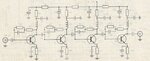
Hello, these two tv class-a amplifiers are from 2 magazines I have found. Both are said to amplify 1mw uhf tv signal to about 100mw.
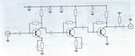
the first one is a 4 stage one and the second a 3 stage.
The first one uses bfr91a for the first two transistors and bfr96s for the final two.
The second one uses bfr96s for the first two transistors and bfq34t for the final one.

I was wondering which one of the two would be better to build (i.e works better)?

The second one (3 stage) is simpler but I see that there are no RFCs, could this work ok?
Also if you add the theoretical transistors amplifications you will find that the second one has only about 32db maximum amplification whereas the first one amplification is tested from the magazine and is about 38db. This means that it must be able to amplify signals as low as 16uW, but the magazine states that its input is about 1mw, so probably there is a mistake there. The other thing is that the 3-stage circuit consumes 100mA @ 12v, whereas the 4-stage one consumes 18v @ 500mA. So I believe the 4-stage one can indeed provide an output of 100mW where as the 3-stage one claim of 100mW is false. They both operate in class-a.
What do you think?
 

Attachments

  • 1.jpg
    1.jpg
    21.3 KB · Views: 206
  • 2.jpg
    2.jpg
    11.6 KB · Views: 140
Last edited:

The Gain 100 is equal to 20dB and 4 transistors are much for this gain.In additional to, 500mA@18V is a huge current consumption for this kind of amplifier.Ther should be a typo error.
A classical wideband TV antenna amplifier consumes around 100mA-150mA @ 6-9V with a pretty good linearity.( Linearity is quite important for these amplifiers because there are many unwanted and interferer signals in the air )
In order to verify SFMDS ( Spruious Free Minimum Detectable Signal ) level, you should know NF and OIP3 point of the amplifier.
The circuits are quite unnecessary complex from my point of view.If you would amplify whole bunch of terresterial TV signals, you should consider a cascode configuration with 2 transistors.It will consume less current and it will also be more linear.
 
  • Like
Reactions: neazoi

    neazoi

    Points: 2
    Helpful Answer Positive Rating
The Gain 100 is equal to 20dB and 4 transistors are much for this gain.In additional to, 500mA@18V is a huge current consumption for this kind of amplifier.Ther should be a typo error.
A classical wideband TV antenna amplifier consumes around 100mA-150mA @ 6-9V with a pretty good linearity.( Linearity is quite important for these amplifiers because there are many unwanted and interferer signals in the air )
In order to verify SFMDS ( Spruious Free Minimum Detectable Signal ) level, you should know NF and OIP3 point of the amplifier.
The circuits are quite unnecessary complex from my point of view.If you would amplify whole bunch of terresterial TV signals, you should consider a cascode configuration with 2 transistors.It will consume less current and it will also be more linear.

Do not get confused, these circuits are not for receiving purposes. These are to be used as TRANSMITTER "power" amplifiers for small TV modulators (<1mw). I think you are talking as if these were receiver preamplifiers.
 

There is always a tradeoff between power gain vs distortion and drive current with power dissipation.

Reducing the supply voltage with a choke on collector improves the tradeoffs. Adjusting the feedback tradesoff the distortion reduction and linearity with lower impedance and drive current.

The emitter resistor improves linearity and optimizes gain power swing for desired load impedance but at the expense of very low input impedance ( 1R)

Here on a simple Java simulation, a single stage provides about 30dB gain with 150mA DC on 3V with 100mW RMS out into 50 Ohms. I have not bread boarded my cheap and dirty design here and some tweaks will be necessary for your device chosen.


In the end 10 to 15 dB power gain per stage is a reasonable compromise. The circuit below is not practical due to input impedance.
CE amp.jpg
 
Last edited:
  • Like
Reactions: neazoi

    neazoi

    Points: 2
    Helpful Answer Positive Rating
There is always a tradeoff between power gain vs distortion and drive current with power dissipation.

Reducing the supply voltage with a choke on collector improves the tradeoffs. Adjusting the feedback tradesoff the distortion reduction and linearity with lower impedance and drive current.

The emitter resistor improves linearity and optimizes gain power swing for desired load impedance but at the expense of very low input impedance ( 1R)

Here on a simple Java simulation, a single stage provides about 30dB gain with 150mA DC on 3V with 100mW RMS out into 50 Ohms. I have not bread boarded my cheap and dirty design here and some tweaks will be necessary for your device chosen.


In the end 10 to 15 dB power gain per stage is a reasonable compromise. The circuit below is not practical due to input impedance.
View attachment 106343

Does it mean that both circuits might work as described, eventhough the second one is much more simple (and without RFCs)
 

The circuits presented are broadband, and seems they are more likely gain-block Class-A amplifiers.
I would go for a narrow-band single stage power amplifier working in AB-Class. With a single BFR96 you can get up to 200mW.
Here is a design example, which can be easily modified for your desired frequency:

https://www.qsl.net/zl1wtt/images/BFR96AMP.gif
 
Without knowing the specs for noise IP3, power dissipation and component values, YES both circuits can work as well as Big Bosses suggestion. More stages should be more linear with less gain and use less current, but without specs, and operating points, these are only hand waving tradeoffs.
 
  • Like
Reactions: neazoi

    neazoi

    Points: 2
    Helpful Answer Positive Rating
The circuits presented are broadband, and seems they are more likely gain-block Class-A amplifiers.
I would go for a narrow-band single stage power amplifier working in AB-Class. With a single BFR96 you can get up to 200mW.
Here is a design example, which can be easily modified for your desired frequency:

https://www.qsl.net/zl1wtt/images/BFR96AMP.gif

Class-AB ? I thought oncly class-A is an option on TV signals amplification. Would class-AB work as well?
 

Class-AB is the power class of most of the RF power amplifiers which are used to amplify digital modulations that require high linearity and reasonable efficiency.
Adjusting the bias point (1k pot in the schematic above) and tuning the output matching network for the right load impedance, it will adapt the linearity of the amplifier for the system requirements.
One stage with BFR96 have about 15dB of linear power gain, and might need to place in front of it a small-signal transistor amplifier.
 
  • Like
Reactions: neazoi

    neazoi

    Points: 2
    Helpful Answer Positive Rating
Do not get confused, these circuits are not for receiving purposes. These are to be used as TRANSMITTER "power" amplifiers for small TV modulators (<1mw). I think you are talking as if these were receiver preamplifiers.
If these circuits are for power amplification purposes, the current consumption is still too high for the mentioned power levels.
Let's say a practical efficiency is %35 and the output power is 100mW.
Output power+dissipated power ( roughly)=300mW @12V
Avarage Current will only be 25mA !!
I guess these amplifiers have been proposed for more output powers. ( 0.5W-1W or more..)
 
  • Like
Reactions: neazoi

    neazoi

    Points: 2
    Helpful Answer Positive Rating
If these circuits are for power amplification purposes, the current consumption is still too high for the mentioned power levels.
Let's say a practical efficiency is %35 and the output power is 100mW.
Output power+dissipated power ( roughly)=300mW @12V
Avarage Current will only be 25mA !!
I guess these amplifiers have been proposed for more output powers. ( 0.5W-1W or more..)

I do not think you can get 0.5W in class-A out of a BFQ34T, it is just too high for thermal package dissipation.
 

  • Like
Reactions: neazoi

    neazoi

    Points: 2
    Helpful Answer Positive Rating
jeez I would not do any of that. I would get one of these:
**broken link removed**

and stick it into one of these:

https://www.ebay.com/itm/Develop-PC...971?pt=LH_DefaultDomain_0&hash=item22f8d1090b


and call it a day

you can either bridge over the spot for the SOT86 amp with a short wire, or pick an SOT86 rf low power amp if you want more gain.

Sure, if an mmic is to be used why not also use the more powerful hybrid modules, getting a whole bunch of watts output. And one could also buy a ready made amplifier for the uhf.
My purpose is to compare the two circuits made out of discrete components.
 

if you are looking for an academic exercise, have at it. If you simply want an amplifier that works, or one that you can actually produce in any quantity, you would use a mmic
 
  • Like
Reactions: neazoi

    neazoi

    Points: 2
    Helpful Answer Positive Rating
if you are looking for an academic exercise, have at it. If you simply want an amplifier that works, or one that you can actually produce in any quantity, you would use a mmic
Sure, I understand you perfectly and this is the case mostly today.
Tell me old fashioned but my point is to have something that can be built even 20 years later and discrete circuits allow this. Even if the transistors become obsolete they can be replaced by similar newer types.
For example the tv modulator I have built (the amplifier is for this one) is a 1977 circuit and I built my version with newer transistors. Not to mention that all UHF and up signals are generated by analogue discrete means super easily. That is the magic of discrete.
Anyway, too much on this issue. :)
I just wanted to compare these two magazine circuits.
 

I just wanted to compare these two magazine circuits.
But the thread topic doesn't seem to match the circuits. You won't use a three or even four stage amplifier for 20 dB gain. Two stage will sufficient for wideband amplifier, single stage might also work with sufficient transistor bandwidth.

And I don't know if you have the necessary information, but we can't because you didn't mention any component values, except for transistor types.
 
Re: Help with 1mw to 100mw uhf TV amplifiers

the first one is a 4 stage one (...)
The first one uses bfr91a for the first two transistors and bfr96s for the final two.
(...) whereas the 4-stage one consumes 18v @ 500mA.

I don't think the 500mA are correct.
BRF91 max. collector current is 50mA
BRF96 max. collector current is 100mA

So the maximum total current would be 2*50mA + 2*100mA = 300mA.
The 18V also don't look right.
 
  • Like
Reactions: FvM and neazoi

    neazoi

    Points: 2
    Helpful Answer Positive Rating

    FvM

    Points: 2
    Helpful Answer Positive Rating
But the thread topic doesn't seem to match the circuits. You won't use a three or even four stage amplifier for 20 dB gain. Two stage will sufficient for wideband amplifier, single stage might also work with sufficient transistor bandwidth.

And I don't know if you have the necessary information, but we can't because you didn't mention any component values, except for transistor types.
I can scan the whole magazine articles but they are in Greek. But you will probably be able to see the component values. I will do so.
 

Status
Not open for further replies.

Part and Inventory Search

Welcome to EDABoard.com

Sponsor

Back
Top