Continue to Site

Welcome to EDAboard.com

Welcome to our site! EDAboard.com is an international Electronics Discussion Forum focused on EDA software, circuits, schematics, books, theory, papers, asic, pld, 8051, DSP, Network, RF, Analog Design, PCB, Service Manuals... and a whole lot more! To participate you need to register. Registration is free. Click here to register now.

Help understanding curve tracer output?

Status
Not open for further replies.

mr_monster

Member level 4
Joined
May 10, 2012
Messages
79
Helped
0
Reputation
0
Reaction score
0
Trophy points
1,286
Activity points
1,964
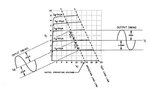
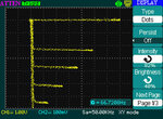
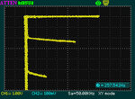
I have recently bought a simple curve tracer made by Leader. It is connected to the scope to use as a monitor. One of the transistors shows normal curves (7), the other one is skipping a few curves (shows 3). What does that mean?
 

Attachments

  • 2n3904.jpg
    2n3904.jpg
    32.1 KB · Views: 90
  • bc109.jpg
    bc109.jpg
    25.3 KB · Views: 84
Last edited:

These curves are upside down compared to how they are normally shown. The second curve is with a transistor with a much higher gain, so the collector current is much higher per step (in your display sitting further down the screen) and the 4th and 5th step are off the screen at the bottom.
Frank
 
  • Like
Reactions: royf

    royf

    Points: 2
    Helpful Answer Positive Rating
Thank you Frank!

I tried moving the graph and increasing to 0.2V/div horizontally but it still does not show more curves...
 

Negative curve is for PNP.. step size is programmable The bigger the output steps indicates higher hFE for that step input. hFE drops with increased current. Flat slope means perfect current source, non flat indicates leakage on current source. step space on output converted to mA divided by step size on input = hFE at that point vs Vce.. A very linear device has flat curves. A very high gain device has big steps on output.. For more resolution,, reduce input step size (mA) and number of steps.
 

step size in this case is 10uA, I should make it smaller? This is the minimum of the tracer... I do have an external bias input (asked about generating a stable low current like that on a different post).
 

no 10uA is fine, then just increase vertical scale with 10 steps as long as SOA is not exceeded on part.
Wounded parts tend to look more leaky.. with more slope on the curve.
An ideal current amplifier {with stepped current controlled input} has a current source output and is flat with infinite impedance.
 

I saw on a curve tracer manual how to measure the non-linearity of a device using the technique shown in the attached diagram, however I can not understand how they select the operating load line the crosses the rated operating voltage. Is this Vcbo? In the case of my transistor that's 30V and the curves are cutting off before that.
 

Attachments

  • non-linearity.jpg
    non-linearity.jpg
    39.8 KB · Views: 74

Status
Not open for further replies.

Part and Inventory Search

Welcome to EDABoard.com

Sponsor

Back
Top