Ulnarian
Newbie level 2
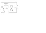
Hey all, I am an extreme beginner to electronics. Anyways, I came across the following schematic and I have a few questions regarding it:

First off, C=Capacitor and R=Resistor (sorry for the crappy diagram )
)
Anyways, this is a circuit which creates a flashing LED.
My questions are this:
1) Why isn't the LED always on? Does the capacitor block the current flow as it charges? If so, what causes the capacitor to discharge? Does it discharge because the supply voltage is brought low when the capacitor is charged triggering the output of the 555?
2) My book says that R1 and R2 control the timing and duration of the flashes. However, why is it necessary to have two resistors here, wouldn't one work just as well?
3) As I understand it, current flows from the positive to the negative, if this is the case, then what happens when the current flowing from the positive terminal of the battery through R3 smacks head on with the current coming out of the output pin (pin 3).
Thanks!
First off, C=Capacitor and R=Resistor (sorry for the crappy diagram
)Anyways, this is a circuit which creates a flashing LED.
My questions are this:
1) Why isn't the LED always on? Does the capacitor block the current flow as it charges? If so, what causes the capacitor to discharge? Does it discharge because the supply voltage is brought low when the capacitor is charged triggering the output of the 555?
2) My book says that R1 and R2 control the timing and duration of the flashes. However, why is it necessary to have two resistors here, wouldn't one work just as well?
3) As I understand it, current flows from the positive to the negative, if this is the case, then what happens when the current flowing from the positive terminal of the battery through R3 smacks head on with the current coming out of the output pin (pin 3).
Thanks!