glenjoy
Banned
- Joined
- Jan 1, 2004
- Messages
- 962
- Helped
- 72
- Reputation
- 146
- Reaction score
- 20
- Trophy points
- 1,298
- Location
- Philippines
- Activity points
- 0
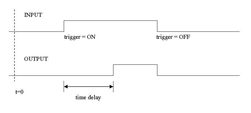
I need a timing circuit with the said output below. You may say this is an ordinary monostable circuit. But this is probably not, the circuit will only change its output after a certain period of time after the user triggers the circuit.
Another difference is that the output is dependent on the users trigger, after the trigger is released (OFF), the ouput immediately follows.
Circuit timing diagram is attached below.
PS.
Let us avoid relays in this design. Time delay is adjusted by an RC, so I think 555 is still applicable.
Thanks.
Another difference is that the output is dependent on the users trigger, after the trigger is released (OFF), the ouput immediately follows.
Circuit timing diagram is attached below.
PS.
Let us avoid relays in this design. Time delay is adjusted by an RC, so I think 555 is still applicable.
Thanks.
")