Continue to Site

Welcome to EDAboard.com

Welcome to our site! EDAboard.com is an international Electronics Discussion Forum focused on EDA software, circuits, schematics, books, theory, papers, asic, pld, 8051, DSP, Network, RF, Analog Design, PCB, Service Manuals... and a whole lot more! To participate you need to register. Registration is free. Click here to register now.

[help] signal conditioning circuit for hall sensor output

Status
Not open for further replies.

etiquoe

Member level 1
Joined
Feb 18, 2010
Messages
35
Helped
4
Reputation
8
Reaction score
1
Trophy points
1,288
Location
Indonesia
Activity points
1,525
hi!

i have 3 phases bldc motor with 3 hall effect sensors inside, for sensing the rotor position. here is the output signal from the hall effect sensors:

46_1286772462.jpg


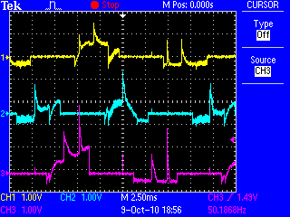
0 v is detected when the sensors detecting one pole of the rotor magnet
and random signal is detected when the sensors detecting another.

i need a signal conditioning circuit to convert the hall effect sensors output to digital signal.
i want convert the 0 volt output to high logic (5 v), and the random signal to low logic (0 v).
got no idea for it.

anyone help please???

regards.
 

A Schmitt trigger won't sort that mess out. You need to sort out the interference first. Have you loaded the hall sensors correctly? Have you run separate power connections to the hall sensors?

Keith
 
No, but the hall sensors get a separate supply to the motor. Have you checked the sensor supply to make sure it is clean (particularly at the motor end)? Have you decoupled the sensor supply?

Keith.
 
Either the motor is badly designed, some sensors are defective or we are mainly seeing measurement artefacts. The waveforms don't look like expectable BLDC sensor output.

I know two types of hall sensors:
- digital sensors with a clear 0/1 output signal. They should show square waves of the fundamental frequency
- analog sensors that should (more or less) show a sine waveform
 

Some sensors need an external pullup resistor. Maybe that is missing?

Keith.
 
No, but the hall sensors get a separate supply to the motor. Have you checked the sensor supply to make sure it is clean (particularly at the motor end)? Have you decoupled the sensor supply?

Keith.


Some sensors need an external pullup resistor. Maybe that is missing?

Keith.

ok, i'll try it
 

this is the datasheet
 

Attachments

  • VEXTA-SpdAxh.pdf
    393.8 KB · Views: 134

That is a motor with controller. Are you trying to run it without the controller or just trying to tap in to the hall signals when it is connected to the controller?

Keith.
 

Are you trying to run it without the controller or just trying to tap in to the hall signals when it is connected to the controller?

Keith.

i'm trying to build my own controller for the motor. so i try to run the motor using my power inverter, applying the commutation step.
when the motor connected to its dedicated controller, the hall sensors output signal is digital (0v/5v). but when i run the motor using my own power inverter, the hall sensors signal output is like i mentioned above
 

OK, I understand. The waveform you show has <0.5V for the hall effect signals so I think the problem is either that you need a pullup resistor to +5V on the hall outputs or that you haven't got the power to the hall devices correct.

Keith.
 
ok, thanks Keith
i'll try to re-check and put pullup resistor

---------- Post added at 08:45 ---------- Previous post was at 08:20 ----------

it works Keith,
:grin:

so grateful
 

Status
Not open for further replies.

Similar threads

Part and Inventory Search

Welcome to EDABoard.com

Sponsor

Back
Top