Continue to Site

Welcome to EDAboard.com

Welcome to our site! EDAboard.com is an international Electronics Discussion Forum focused on EDA software, circuits, schematics, books, theory, papers, asic, pld, 8051, DSP, Network, RF, Analog Design, PCB, Service Manuals... and a whole lot more! To participate you need to register. Registration is free. Click here to register now.

help required for making a h-bridge.

Status
Not open for further replies.

tehmaas hasan

Junior Member level 1
Joined
Mar 21, 2012
Messages
19
Helped
0
Reputation
0
Reaction score
0
Trophy points
1,281
Activity points
1,414
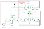
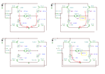
i want to make a h-bridge using 4 npn 2n222a transistors.

need a suitable schematic.
help required as soon as possible.

thank you.
 

yes in the first part i have no confusion but in the second part why 2 npn and 2 pnp transistors are used.

cant understand the concept of 2nd schematic. 1st one is ok.

one question arises in my mind in the 1st schematic why the base pin is not connected. or where is its possible connection.
 

Bases go to control circuit.

Its NPN and PNP examples.

Motor go forward T1 = 1, T2 = 0, T3 = 0, T4 = 1
Motor go Backwards T1 = 0, T2 = 1, T3 = 1, T4 = 0
Motor idling T1 = 0, T2 = 0, T3 = 0, T4 = 0
Motor brake (quick slowdown) T1 = 1, T2 = 0, T3 = 1, T4 = 0
Brake T1 = 0, T2 = 1, T3 = 0, T4 = 1

Avoid T1 = 1, T2 = 1 this would be bad, the same is for T3 = 1, T4 = 1. It would cause both transistors to come on giving a direct path to ground. The transistors would burn up, and you could damage your power source.

T1 and T2 are on left side, T3 and T4 are on right side.
T1 and T3 are on top side, T2 and T4 are bottom side.
 
Last edited:
but if it is possible with 4 npn why we use 2 npn and 2 pnp.?
 

We use lots of things. There is many H-Bridge designs.


Answer is in post 4:
"Avoid T1 = 1, T2 = 1 this would be bad, the same is for T3 = 1, T4 = 1. It would cause both transistors to come on giving a direct path to ground. The transistors would burn up, and you could damage your power source. "

Also add diodes across each transistor, anode to the emitter 1N4007.
 
Using PNP's allows you to not need a high voltage-capable driver circuit to turn on the upper NPN's in the bridge. Instead, all you'd need to do is pull the base of the PNP's below Vcc-0.7V (you can choose any circuit you like to accomplish that).

FETs are easier to use in an H-bridge, then you just need to supply voltages and don't need to mess around with tweaking the base currents to get both BJT's into saturation. That's just a personal preference after messing around with a few of these circuits over the years.
 
It's better to use npn+pnp, because you drive BJTs with current through emitter and base. With npn high side switching you would need driver circuit which maintains desired base current regardless of emitter potential. There's no reason to use npn bjt for a high side switch. People generally used n-channel mosfet for high side switching because they typically exhibit much lower Rds_on than equivalent technology/price mark p-channel mosfets. Of course you can buy low rds-on p-channel ones, but in many cases they are more enxpensive than n-channel+bootstrap driver.
 
The difficulty is that either of the first two basic bridges can still smokeshow if both sides of the bridge are triggered at the same time. For a more stable, generic motor controller, the following does the job.. :-D
 

Attachments

  • Smoke proof H bridge.png
    Smoke proof H bridge.png
    53.3 KB · Views: 114

For the first thing you need to add some resistors in series with base. Base-emitter junction is essentially a diode, co some means of current limiting are necessary. Otherwise you're gonna smoke your transistors.
 

@tehmaas hasan

For the classical PNP-NPN bridge you need to use two more transistors. See the design I have proposed in the previous post. Don’t be scared about additional resistors and diodes, this will help you to complete a fail-proof bridge. :-D
 

I added 4 resistors of 1 k ohm but the motor was not spinning I don't know why? but when I removed the resistors motor starts revolving as desired. but very slow rotation was observed.
 

Did you check the circuit simulation?
 

Attachments

  • Motor test.png
    Motor test.png
    149.6 KB · Views: 103

https://obrazki.elektroda.pl/23_1337855367.jpg

I have made a h-bridge without base resistors it is working fine on proteus simulation i have a normal motor of DC 6 volts. the problem is that it is revolving very slow in both the directions. and if I place resistors in the circuit the motor does not tends to move even.

so what can I do to rotate the motor in a sufficient speed. And why the base resistance is affecting the speed. I have seen most of the schematic with 1 k ohm resistance on base terminals of each transistors.
so should I place while implementing on bread board or not.

---------- Post added at 15:43 ---------- Previous post was at 15:38 ----------

i have also made one circuit by decreasing the resistance up to 0.5ohm

still the motor is moving very very slow.

https://obrazki.elektroda.pl/49_1337856178.jpg
 

I have simulated your circuit and there’s a major fault in that design.
See the previous diagram. There’s very large current flowing through the bipolar transistors and there is no current passing through the motor as required.
:cool:
 

Hello friend,

Why do not use you mosfets, and low-high side dirvers for each arm of the bridge???

Please view the other threads in this forum... to help you!

HTML:
https://www.edaboard.com/threads/219997/

Good job!

Basofias
 

Status
Not open for further replies.

Similar threads

Part and Inventory Search

Welcome to EDABoard.com

Sponsor

Back
Top