Continue to Site

Welcome to EDAboard.com

Welcome to our site! EDAboard.com is an international Electronics Discussion Forum focused on EDA software, circuits, schematics, books, theory, papers, asic, pld, 8051, DSP, Network, RF, Analog Design, PCB, Service Manuals... and a whole lot more! To participate you need to register. Registration is free. Click here to register now.

help - recommendation for paralleling mosfets

Status
Not open for further replies.

anotherbrick

Full Member level 4
Joined
Jan 10, 2009
Messages
217
Helped
1
Reputation
2
Reaction score
1
Trophy points
1,298
Location
Istanbul , Turkey
Activity points
3,142
hello dear forum members ,

I have a half bridge of IRFP460
DC link voltage is 310 V

I drive 1 KW of ultrasonic piezo transducers with this Half bridge -there is coupling trafo at the output of the half bridge and impedance matching inductance in series with piezo's at the output of trafo

however at 3.5 A input power the upper mosfet case temp is 120 degree Celcius

first question = why is the upper mosfet heating more than lower mosfet ?

second - to decrease the case temperature I paralleled 2 mosfets up and 2 mosfets down

this time when I turn the generator on - 1 upper and 1 lower mosfest blow up

my question : how can I make parallel mosfets work reliablely ?

I drive gates with IR2113 - I tried 30 ,150,220 ,270 Ohm gate resistors - cant get rid of heating

please help , thank you

ultrasonic4.JPG
 

Hi,

There are a lot of forum threads discussing half bridge circuits.

There are several cases that causes heating of a fet.
Too high rds-on with too much current.
Low gate drive voltage
Slow turn on and turn off switching
Crossconducting because of slow switching
Cross conducting because of slow body diode....
And so on

Klaus
 
hello thank for the answer

my aim was to ask about gate drive circuitry

what shall I add to gate - source circuit other than

gate resistor for safety of mosfets

becouse only with gate resistor 2 mosfets blow up during operation or by

start of generator with 4 mosfet half bridge

PS. I have added seperate gate resistor for each mosfet it didnot any help
 

What gate resistor values do you have? The upper mosfet gate drive is probably less ideal.

What's your cooling solution? Does it cool the upper and lower fets equally?

It's much preferable to 1) Clean up the driving circuitry 2) Add additional cooling/heatsinking 3) Move to larger package before adding a parallel mosfet.
 
I drive gates with IR2113 - I tried 30 ,150,220 ,270 Ohm gate resistors

everytime the case temp of upper mosfet reached ~110 -120 degree Celcius at about 3.5 A power input at the 220 VAC mains

lower mosfet is cooler ? why? - I dont know

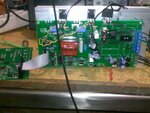
here the photo of my generator

dont confuse by the the wires to the gates
gate lines are on the PCB now

31102014143.jpg

I cannot change the PCB in short time
my customers waiting for the generators at once

what else shall I put to gate circuit more other than gate resistors , for safe operation , with parallel mosfets ?
 

The selective heating of highside transistors can be e.g. caused by
- asymmetrical control waveform, particularly different deadtime or duty cycle
- asymmetrical circuit layout, causing respective differences in circuit inductance
- insufficient bus voltage bypassing

Probing transistor voltages and currents should reveal how it's brought up.
 
hello thank all

please I am not asking heat problem

I am asking what else shall I put to gate circuit other than gate resistors , for safe operation , with parallel mosfets ?
 

Hi,

Smaller gate resistors should minimize crossconducting.....if this is the problem.

Klaus
 
The surest fix is to put a small dual gate drive chip (8 pin) between the 2113 and the 2 upper fets (and 2 lower fets) this way they cannot interfere with each other at turn on and turn off, Ron = 15 ohm and a back diode (schottky 40V, 1A) for turn off, also you will isolate issues from the dv/dt of the mid point of the fets if you do this.
Use 1uF to 10uF de-coupling on ALL the gate drive chips, make sure the dead time is adequate for your driving signals (at least 250nS)
Good Luck...!

also - just noticed from your photo, if your gate drive is too far away, say > 2cm, you need tight twisted wires to go from the gate driver (G-S) to the gate and source of the fet - this might be the root cause of your problems....!!!!
 

Status
Not open for further replies.

Similar threads

Part and Inventory Search

Welcome to EDABoard.com

Sponsor

Back
Top