Continue to Site

Welcome to EDAboard.com

Welcome to our site! EDAboard.com is an international Electronics Discussion Forum focused on EDA software, circuits, schematics, books, theory, papers, asic, pld, 8051, DSP, Network, RF, Analog Design, PCB, Service Manuals... and a whole lot more! To participate you need to register. Registration is free. Click here to register now.

Help reading schematics - artificial ventilator for someone

Status
Not open for further replies.
Rather than a blower I'm picturing a plastic bag pressed by a rolling cylinder at 5 or 10 seconds per cycle (normal breathing rate).

1) The roller pushes a single breath into the lungs. Air goes out a tube to the mask. (Add an oxygen feed if possible.)

2) As the roller returns to its original position, the bag fills with exhaled air. This gives a clue that the patient is breathing air out.

3) A valve activates, the roller pushes used air out of the bag to cleansing.

4) A valve activates, the roller returns to its original position as the bag fills with fresh air.


----------------------

There are oxygen concentrators available for homebound respiratory patients. These are expensive new, but you might find a used one cheap. It may be an alternative to an oxygen tank.
 

In this particular case, excess pressure to force air into the lungs may not be very effective. If my understanding is correct, the lungs are already clogged with mucous.

It is better to apply suction to remove exhaled air and then allow normal air to get in by its own. This negative pressure can help better oxygen saturation.

If some cases are this way I wasn't aware of it. I once had pneumonia. It was fatiguing. At times it was an effort to inhale. I wished I had an airpump pushing breath into my lungs.

Now in later years I still have times like that, especially if I've been putting on weight.
 

Rather than a blower I'm picturing a plastic bag pressed by a rolling cylinder at 5 or 10 seconds per cycle (normal breathing rate).

Isn't that like the bag paramedics use and squeeze? There are ideas here, but IMHO I wouldn't like to be hooked up to one. I like the idea of hooking something up to a resus dummy though.

https://www.instructables.com/id/The-Pandemic-Ventilator/
https://hackaday.com/2020/04/09/what-does-a-dependable-open-source-ventilator-look-like/

It might be easier to learn how to take blood plasma with antibodies from a recovered COVD-19 patient and put it back in your body. The stats are showing that 50% of patients put on a ventilator die, which doesn't seem that good? In UK doctors are writing to care homes telling managers they don't want their (old) ill residents transferred to hospital using up their scarce ventilators.
 

Isn't that like the bag paramedics use and squeeze?

Exactly!

That is a manual version of the celebrated ventilator. In the manual version, you get a feedback from the patient visually; you see how the fellow is responding.

The stats are showing that 50% of patients put on a ventilator die

I shall not be surprised if the numbers are more than 50% (in other words, some may survive in spite of the ventilator!).

But then I am not a medical professional. But please tell me why ventilators need to be so expensive?
 

UPDATE:

I understand everyone's concerns on why a blower and why not an actual ventilator, I decided to continue this blower, the person I was building this for is safe, so for the ventilator comments please open another thread, I am interested in a ventilator as well!, I just want to finish this stupid blower home project first and then start the ventilator.

I am struggling with the schematics again, I think they are not very clear, or perhaps, most likely I have no skills yet on this.

I have done all the schematics so far, I have a very basic question I think, I have one cable I am not sure if should be also grounded, I have issues understanding this part of the schematics.
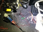
This is what I have done so far:
95108455_3917732434935880_2008351858938085376_n.jpg

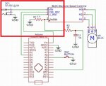
In the below section of the schematics, I can't identify the red and black cables that goes to the Power Adaptor, the red seems to be straightforward and well connected... the black, seems to be only going to the BLDC however I think it should also be connected to all the other GROUNDed cables in the circuit?
95410384_160529178735536_7444239636156645376_n.jpg

I turned ON my current project, I can only hear the Arduino Nano3 beeping every 2 seconds continuously, so I feel something else is needed here. It should start blowing and the SW switch should regulate the blower speed.
 

Attachments

  • schematic_20200317.2.jpg
    schematic_20200317.2.jpg
    146.3 KB · Views: 131

Hi,

There is a symbol "GND" in the schematic. Several indeed.
This symbol is a "shortcut" for all Ground connections. This helps to reduce wires that are spread all over the schematic, it makes schematics more easy to read.

In a real wiring all these GND need to be connected. Often a black wire is used.

Klaus

Thank you KlausST,

I would assume these BLDC boards already are connecting the below "GND" so I don't need to do any extra wiring here then.
94616204_2876884599015948_6135962318275608576_n.jpg
 

Hi,

Look at the schematic.
None of the BLDC_driver board signals are directly connected to GND.

Only one signal (GNDIN) is connected via external shunt (R1) to GND. This I can´t find on your pictures at all.

There may be more issues.

Klaus
 

Hi,

Look at the schematic.
None of the BLDC_driver board signals are directly connected to GND.

Only one signal (GNDIN) is connected via external shunt (R1) to GND. This I can´t find on your pictures at all.

There may be more issues.

Klaus

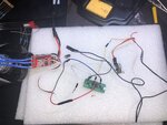
Thanks again KlausST, yes you are 100% correct, I skipped that resistor as well, I have now done it, and using that new knowledge, I have check all the rest of the circuit and it seems now correct.
94887668_526615498012026_2914015622482362368_n.jpg
The only issue I have now is the Motor, it seems the motor is beeping only, not actually working, I did a research on this, it seems the Arduino code I have is not initializing my Motor how it should.

What are the basics when working with Brushless motors and Arduino? is there any code I can have a look at to kick start my motor properly?

My Motor is this one **broken link removed**

And the code I am using is:

My question would be only, if there is anyone with Arduino experience and Motors, for every brushless motor the code should change? I was under the impression that no change is needed?

Code:
#include <Servo.h>

Servo myservo;  

//some variables to tweek
#define version "20200316.2"
#define rate 16 // breathing cycles per minute
#define enable_motor true // useful for debugging without noise

#define max_speed 180
#define min_speed 0
#define PEEP_speed 40 //approx 5cm/H2O
#define led_pin 13
#define button_pin A5
#define current_pin A0
#define servo_pin 3
#define serial_baud 9600

int buttonState = 1;
int buttonStatePrev = 1;
int speed_state = 0;
int loop_count = 0;
int click_loop_count = 0;
int click_count = 0;

int target_speed_high = 0;
int target_speed_low = 0;

int cycle_counter = 0;
int cycle_phase = 0;
int mode = 0;
int current = 0;


void setup() {

  Serial.begin(serial_baud);
  Serial.print("Version:\t");
  Serial.println(version);

  pinMode(led_pin, OUTPUT);
  pinMode(current_pin, INPUT);
  analogReference(INTERNAL); // sets reference to 1.1v
  pinMode(button_pin, INPUT_PULLUP);
  digitalWrite(led_pin, HIGH);

  if(enable_motor){
    myservo.attach(servo_pin,1000,2000); // some motors need min/max setting
    
    Serial.print("Initializing ESC...");
    
    myservo.write(max_speed);
    delay(3000); // wait for esc to boot, and sample maximum
    myservo.write(min_speed);
    digitalWrite(led_pin, LOW);
    delay(2000);  // wait for esc to sample minimum

    digitalWrite(led_pin, HIGH);
    myservo.write(PEEP_speed);
    Serial.println("Done");  
  } else {
    Serial.println("Motor disabled.  Bypassing initialization");      
  }
}

void loop() {

  buttonStatePrev = buttonState;
  buttonState = digitalRead(button_pin);

  // button down event, accumulate number of clicks and time of first click
  if(buttonState == 0 and buttonStatePrev == 1){
    click_loop_count = loop_count;
    click_count += 1;
  }

  if(click_count > 0){
    // past click count timeout
    if(click_loop_count + 30 < loop_count){
      if(click_count == 1){ // single click
        speed_state = (speed_state + 1)%5;
        if(mode == 0){
          cycle_counter = 10000; // if in CPAP mode update immediately
        }
      }
      if(click_count == 2){ // double click
        mode = (mode +1)%2;
        // if entering PEEP mode, update immediately in exhale cycle
        // otherwise, maintain phase
        cycle_phase = 0;
        cycle_counter = 10000;
      }
      // blink LED
      digitalWrite(led_pin, LOW);
      delay(50);  
      digitalWrite(led_pin, HIGH);

      // print state
      Serial.print(loop_count/100.0);
      if(mode == 0){
        Serial.print("\tset to CPAP level: ");
        Serial.println(speed_state);
      }
      if(mode == 1){
        Serial.print("\tset to PEEP level: ");
        Serial.print(speed_state);
        Serial.print("\tforced rate: ");
        Serial.print(rate);
        Serial.println("/min");
      }
      click_count = 0;
    }
  }

  // approximate pressure mapping fro original blower. Other blowers will vary
  // 40 ~= 5cm/H2O
  // 60 ~= 10cm/H2O
  // 90 ~= 18cm/H2O
  // 120 ~= 32cm/H2O
  
  if (speed_state == 0) {
    target_speed_high = 60;
    target_speed_low = PEEP_speed;
  }
  if (speed_state == 1) {
    target_speed_high = 70;
    target_speed_low = PEEP_speed;
  }
  if (speed_state == 2) {
    target_speed_high =  80;
    target_speed_low =  PEEP_speed;
  }
  if (speed_state == 3) {
    target_speed_high =  90;
    target_speed_low =  PEEP_speed;
  }
  if (speed_state == 4) {
    target_speed_high =  100;
    target_speed_low =  PEEP_speed;
  }
  
  //CPAP mode, both speed are the same
  if(mode == 0)
    target_speed_low = target_speed_high;
    
  // handle breath in/out cycle at target rate/min
  cycle_counter += 1;
  if( (30*100)/rate < cycle_counter){
    cycle_phase = (cycle_phase+1)%2;
    cycle_counter = 0;
    Serial.print(loop_count/100.0);
    Serial.print("\tphase speed:");
    if(cycle_phase == 0){
     if(enable_motor)
        myservo.write(target_speed_high);
      Serial.println(target_speed_high);
    } else {
     if(enable_motor)
        myservo.write(target_speed_low);
      Serial.println(target_speed_low);
    }
  }

  // for debugging breathing back pressure sensing
//  current = analogRead(current_pin);
//  Serial.print(current);
//  Serial.print(",");
//  Serial.println(digitalRead(button_pin));
  
  loop_count += 1;
  delay(10);  // approximately 100 cycles per second
}
 

Hi,

I don´t think your wiring is correct, But I can´t verify it because we don´t see where all the (black) wires go to.

What value is your resistor? It looks like 100 Ohms, but it should be 0.1 Ohms.

Klaus
 

Hi,

I don´t think your wiring is correct, But I can´t verify it because we don´t see where all the (black) wires go to.

What value is your resistor? It looks like 100 Ohms, but it should be 0.1 Ohms.

Klaus

Yeah, the resistor is wrong, I will go and try to find one of these, I made the wrong conversion from Komh to omhs and now I have a good resource here
I will buy this one on Tuesday, public holidays here in Australia.
RR3206-0-1-ohm-5-watt-wire-wound-resistorImageMain-515.jpg

I have corrected my wires, now all GND are black.
95259659_540940053279635_4643196256447889408_n.jpg

I will update this thread once I get the correct resistor.
 

Hi,

still your wiring is not correct.

In your picture I see the black wire from your power supply (which should be GND) directly connected to the BLDC board (which is not correct).

--> according schematic: BLDC has neither a dircet connection to system GND nor to the power supply_GND.

Klaus
 

Status
Not open for further replies.

Part and Inventory Search

Welcome to EDABoard.com

Sponsor

Back
Top