Continue to Site

Welcome to EDAboard.com

Welcome to our site! EDAboard.com is an international Electronics Discussion Forum focused on EDA software, circuits, schematics, books, theory, papers, asic, pld, 8051, DSP, Network, RF, Analog Design, PCB, Service Manuals... and a whole lot more! To participate you need to register. Registration is free. Click here to register now.

Help power electronic :(

Status
Not open for further replies.

jokerx

Newbie level 6
Joined
Feb 13, 2012
Messages
13
Helped
1
Reputation
2
Reaction score
1
Trophy points
1,283
Activity points
1,361
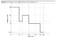
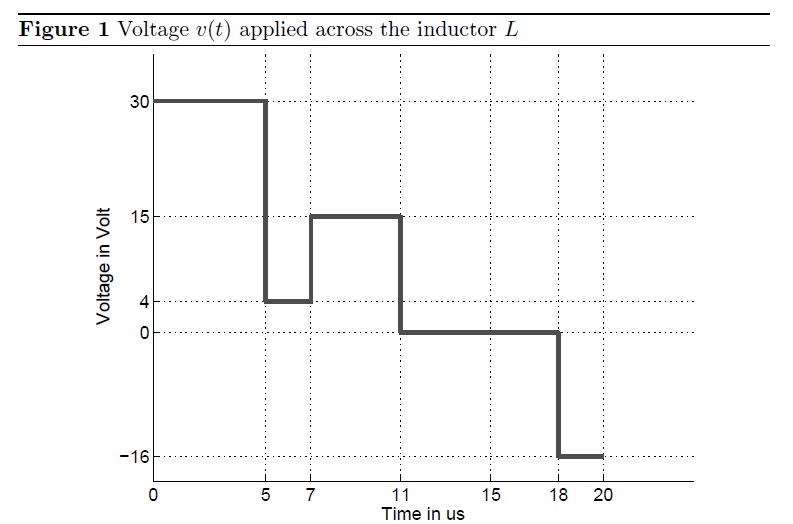
A time varying voltage v(t) as shown in figure 1 is connected across an inductor
L with a value of 200 μH. The inductor current iL at t = 0 is 0.5 A. How much
energy is stored at t = 20 μs?

given graph:


please help asap:|
 

Current will not jump instantly through an inductor immediately when voltage is applied.

So to solve the problem with the given information, we have to assume the current was already at equilibrium (.5A at 30V) prior to t=0.

This implies a coil resistance of 60 ohms (30 V divided by .5A).

Energy stored at t=0 is 100 microWebers. (L*A)

The formula to obtain time constant is L/R. 200 uH divided by 60 is 3.33 uSec.

The rest of the work involves plotting a graph of inductor response from one uSec to the next. There is no change for the first 5 uSec. (Unless I've made a wrong assumption somewhere.)
 

I don't think there is a resistance in the problem. Once you are given the voltage across the inductance and the inductance value, you can figure out the inductor current slope. Since vL= L diL/dt, this implies that diL/dt = vL/L. So if you take the given plot and divide it by the inductance you have the slope of the current at any time. You have to begin with the given 0.5A at t=0 and draw the slopes to get the shape of the inductor current. Higher diL/dt value means higher slope. Positive diL/dt gives positive slope and negative diL/dt gives negative slope. There is no resistance or time constant involved in this problem at all. Also the energy is not given in Webers. Webers is the unit of flux linkage and not energy which must be in Joules. The energy in the inductor at 20us is 0.5*L*(iL(20us))^2. So if you know the inductor current at 20us, you will be able to figure out the energy at that time.

Best regards,
v_c

I acknowledge you are correct. You present the math and explanation convincingly.

I can recognize you are correct because I have observed that inductor current flow starts responding at a rate which depends on the Henry value. When the resistance is high, the plot levels off quickly because the target current is low. With low resistance the plot continues on the characteristic curve. Nevertheless both plots overlap up to that point.

I should learn the formula for joules. I use webers because it is more specific to inductor dynamics, and lends itself to calculating counter-emf easily.
 

Status
Not open for further replies.

Similar threads

Part and Inventory Search

Welcome to EDABoard.com

Sponsor

Back
Top