Continue to Site

Welcome to EDAboard.com

Welcome to our site! EDAboard.com is an international Electronics Discussion Forum focused on EDA software, circuits, schematics, books, theory, papers, asic, pld, 8051, DSP, Network, RF, Analog Design, PCB, Service Manuals... and a whole lot more! To participate you need to register. Registration is free. Click here to register now.

[HELP] p18f4520 programming issues

Status
Not open for further replies.

Rollanddie

Newbie level 4
Joined
Feb 10, 2016
Messages
6
Helped
0
Reputation
0
Reaction score
0
Trophy points
1
Activity points
43
Hi everyone! I'm new to programming and would like to seek the advice of you guys here

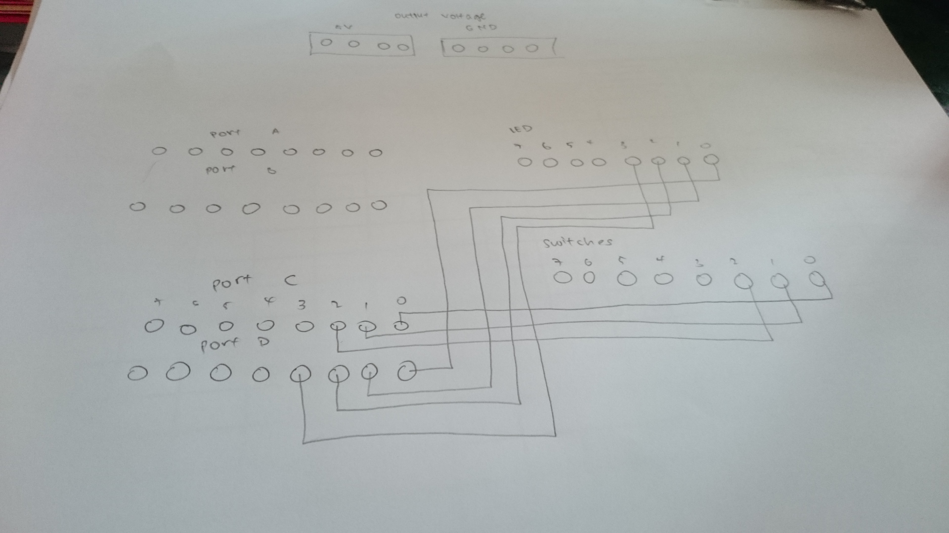
Currently I'm on a project to make up to 4 motors run and up to 4 LEDs to light up concurrently. My program is as follows:


Code C - [expand]
1
2
3
4
5
6
7
8
9
10
11
12
13
14
15
16
17
18
19
20
21
22
23
24
25
26
27
28
29
30
31
32
33
34
35
36
37
38
39
40
41
42
43
#include <p18f4520.h>
#include <delays.h>
 
#pragma config OSC = HS
#pragma config WDT = OFF
#pragma config LVP = OFF
#pragma config PBADEN = OFF
 
#define S0  PORTCbits.RC0
#define S1  PORTCbits.RC1
#define S2  PORTCbits.RC2
 
void main(void)
{
TRISD = 0x00; //output
TRISC = 0xff; //input
PORTD = 0b00001111;
 
 
while(1)
{PORTD = 0x00;
if((S0==1)&&(S1==0)&&(S2==0))
{
PORTD = 0b00000001;  //led 0 to light up
[B](Motor 1 to run)[/B]
}
else if((S0==0)&&(S1==1)&&(S2==0))
{
PORTD = 0b00000011;  //led 0,1 to light up
[B](Motor 1&2 to run)[/B]
}
else if((S0==1)&&(S1==1)&&(S2==0))
{
PORTD = 0b00000111;  //led 0,1,2 to light up
[B](Motor 1&2&3 to run)[/B]
}
else if((S0==0)&&(S1==0)&&(S2==1))
{
PORTD = 0b00001111;  //led 0,1,2,3 to light up
[B](Motor 1&2&3&4 to run)[/B]
}
}
}


Those in BOLD tags is what I need help with. Can I use a same switch to control both the LED and motor?


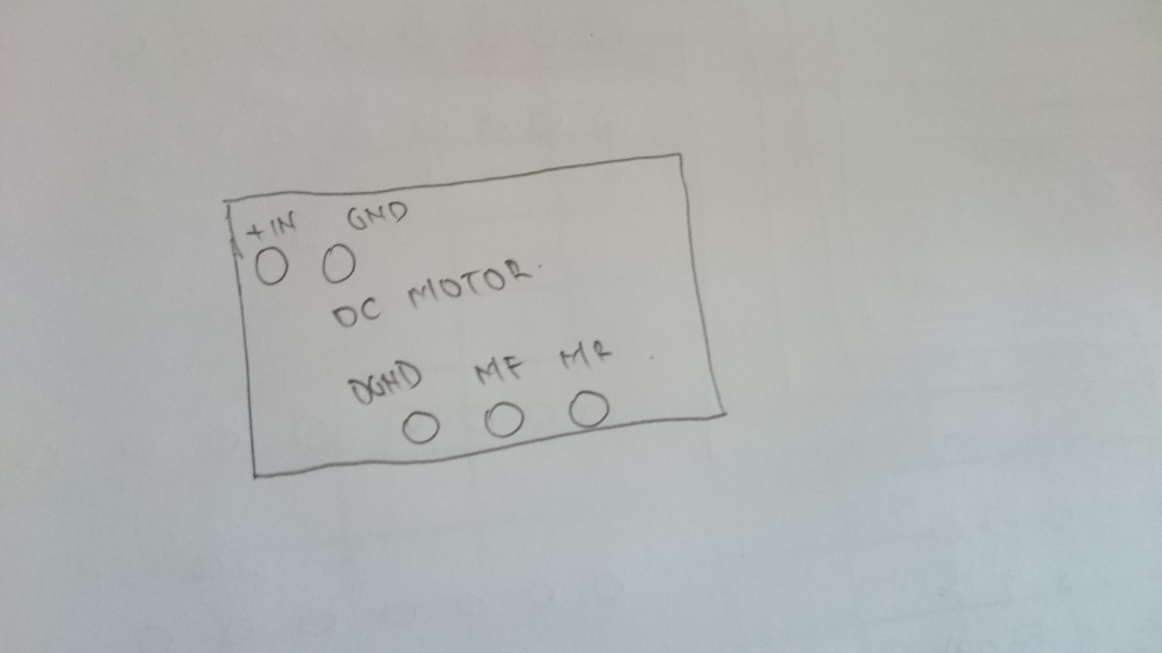
Using a simple DC motor with 5V, GND, MF, MR

- - - Updated - - -

Appreciate any inputs! :)
 
Last edited:

dear its not a difficult job to run motor and LED concurrently.
Can you share the connection diagram.
actually i am not familiar with the motors.
otherwise as you defined S0, S1 and S2, you can define LEDs and motor ON/OFF pins.
just set them when you want to run them.

yes you can use same switch for LED and motor but you have to care about the current flow
by selecting appropriate resistors.
 

Sorry but I do not have or know how to do the connection diagram. Am quite new to programming. The whole idea of the project is a fan controlled by temperature.

Once sensors detect temp at certain degrees, it will trigger the motor to run. The higher the temp, the more motors will run(up to 4 motors). LEDs to light up according to how many motors running

But sensors are not provided for testing so we may use switches as replacement.

As you said defining the LEDs and motor on/off is to define them individually? I tried but It works for the LED but doesn't work for the motors..
 

Hi,

Sorry but I do not have or know how to do the connection diagram.
I´m sure you can draw a simple draft where we see each PIC pin with it´s connected circuit.

It´s what you made with your blue wires....just painted on a paper (or PC)

Klaus
 

And the dc motor will be something like this


Hi,

you really don´t know the schematic symbol of a
* resistor
* capacitor
* LED
* motor
* VCC
* GND
*...

And you never have seen a circuit diagram... to copy it somehow?

****
If you want to go on with microcontroller programmin..this is urgent knowledge.
I strongly recommend to learn these things.
There is no need for a perfect circuit diagram... but at least for your own documentation sooner or later you will need it.

For your own ... and it is more important when you want to communicate with other persons about your circuit and programming.

****
A simple example with your question:
How to light a LED?
--> It depends how it is connected. For sure it is connected to a port pin.. but then.. It could be connected (with series resistor)
* and cathode to GND or
* anode to VCC

And this makes a big difference how your programming should be, because the LED light either with a HIGH on the port output or a LOW on the port output.

--> The circuit shows the programmer if he needs to output LOW or HIGH to light up the LED.

Klaus
 

Hi, I'm new to microcontroller programming and has not gone into the circuit diagram part
 

You need to study the basic language of electronics so that you can communicate with others. It is not at all difficult (if I can do it, anybody can do it) but you need to devote some time and effort to learn. It is certainly not essential to be perfect but did you write the code fragment yourself or did you simply copy it from some other place? Are you familiar with programming languages? If you are specific with the question, we can also be specific with the answers.

Steps:

Objective: give a brief detail

Methodology: how you intend to reach your goals

Obstacles: specific areas you are having difficulties

Help: Spell out the problem as clearly as possible because although we all see the same sentence, we understand little differently. That is a good thing because we suggest improvements in different ways.
 

Status
Not open for further replies.

Similar threads

Part and Inventory Search

Welcome to EDABoard.com

Sponsor

Back
Top