Continue to Site

Welcome to EDAboard.com

Welcome to our site! EDAboard.com is an international Electronics Discussion Forum focused on EDA software, circuits, schematics, books, theory, papers, asic, pld, 8051, DSP, Network, RF, Analog Design, PCB, Service Manuals... and a whole lot more! To participate you need to register. Registration is free. Click here to register now.

Help Needed with Load Cell Project and Op Amp gain configuration OP07/TL081

Status
Not open for further replies.

dtomazini

Newbie level 5
Newbie level 5
Joined
Aug 6, 2013
Messages
8
Helped
3
Reputation
6
Reaction score
3
Trophy points
3
Location
Brasil
Visit site
Activity points
95
Hi Everybody,


I'm new in this forum, and new to Op Amp.

A two weeks ago, I'm trying to build a simple weight measure project, using a load cell from a 10Kg kitchen scale and a PIC18F4550. My project did not work. But i don't understood what is going wrong.

Searching in this forum, and Google, i found lot information about load cells and Op Amps. But in almost cases, the op amp used like INA125, AD620, AD623 is hard to find and much expensive here in Brazil.

The first step in my project, is know the load cell that I'm using. For that i use a multimeter, to measure the resistance between connectors, and the voltage in load and unload:

Resistance in terminals:
"Excitation+" to "Excitation-" = 1K
"Signal+ " to "Signal -" = 1K
"Signal+ " to "Excitation-" = 750R
"Signal-" to "Excitation+" = 750R


Voltage (using a 5.45v power source) in terminals SIG+ and SIG-:

Without load: 0,001v
At full load 10kg: 0,055v


To confirm the measuring scale voltage, i repeat the test using a 9.4v power source, an result was:
Without load: 0,001v
At full load 10kg: 0,094v


So after this tests, the conclusive schematic for my load cell is:


Please, can someone tell if this schematic is correct ?. And presume the scale of 1mv/V ?.


The second step, was try to use a Op Amp in "Differential" to amplify the voltage between SIG and SIG- for the PIC18F4550 ADC module .

Now is the problem...I try a LOT of schemas, formulas, Inverting, Non-inverting, Differential, Differential Instrumental, etc... and have nothing.

In my lab (house), I have the following Op Amps:

Single:
UA741CN
TL081
OP07
LM318
LM301AN

Dual:
TL082
LM358

None of them work's as expected... or the voltage is saturated at 4.8v, or stuck in 1.28v, or simply did not respond for the load cell load alternations.

Tried Schematics:

Diferential Op Amp ("SIG+" - "SIG-"), Gain Vo/Vi = 10:


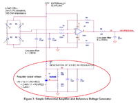
Similar project from this link: https://www.galant-e.ru/images/upload/1875/ru/an_651x_011%20-%20rev%201-3.pdf
 

Gain setting resistors should be 10x bigger (15K, 150K). Now You supply too much additional current to bridge which makes it unbalanced. Add decoupling capacitor to opamp supply. Don't expect some great accuracy.
For better accuracy You should use instrumentation amplifier.
 
You might find the following Analog Devices document of interest, it covers bridge circuit design using both general and instrumentation OPAmps:

BRIDGE CIRCUITS

BigDog
 
It looks like you don't understand yet the restrictions of single supply OP circuits. Although I basically agree with GUMY's suggestions, a simple single OP amplifier as shown in post #1 can work. But it must be biased for an output voltage level inside the OP's linear range. Your circuit would give zero output for balanced load cell, which isn't possible with single supply. You can however shift the zero output to mid supply (or 1-2 V, depending on the used OP) by replacing the 15k resistor with a 30k+30k voltage divide.

Another point is that most OPs aren't guaranteed to work at all with 5V supply voltage.

OP07 is typically working with 5V, but guaranteed minimal supply voltage according is 6V (+/- 3V). So the said "similar" circuit from the link will probably work, because it has a suitable bias that's missing in your design, but at worst case, it might fail too.
 
Last edited:
Agree with FvM. You should use single supply opAmp. The only one in Your portfolio is LM358. This one goes down to 10mV output if Your load is less then 10uA and supply can be down to 3V. But the precision willl be poor as it has several mV of offset voltage.
 
Thank´s for the answers !!.

I try to add two decoupling Capacitor of 100nf, and modify the resistor to have a gain [Vout/ (SIG+ - SIG-)] of 1x but...in all tests the Vout is satured.

Test Results:

741CN - 4,59v
TL081 - 4,51v
301AN - 4,60v
OP07 - 4,59v

Schematic used:


So, i belive is better take a look in the recomended bigdogguru article, before try another schematic.


Thank´s
Daniel
 
  • Like
Reactions: siva88

    siva88

    Points: 2
    Helpful Answer Positive Rating
Besides the low pass filters, I believe you will also need to shift the output utilizing a proper bias as FvM has suggested.

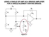
Reference: Bridge Circuits, Section: AMPLIFYING AND LINEARIZING BRIDGE OUTPUTS, Page: 2.7
AMPLIFYING AND LINEARIZING BRIDGE OUTPUTS

The output of a single-element varying bridge may be amplified by a single precision
op-amp connected in the inverting mode as shown in Figure 2.7. This circuit,
although simple, has poor gain accuracy and also unbalances the bridge due to
loading from Rf and the op amp bias current. The Rf resistors must be carefully
chosen and matched to maximize the common mode rejection (CMR). Also it is
difficult to maximize the CMR while at the same time allowing different gain
options. In addition, the output is nonlinear. The key redeeming feature of the
circuit is that it is capable of single supply operation and requires a single op amp.
Note that the Rf resistor connected to the non-inverting input is returned to Vs/2
(rather than ground) so that both positive and negative values of ∆R can be
accommodated, and the op amp output is referenced to Vs/2.


As you indicated you are attempting to interface this circuit with a PIC18F, are Microchip OpAmps available in Brazil?

Microchip OpAmps Products

**broken link removed**

Their pricing is typically in the $0.50 to $1.00 range, operate with a single supply at the required operating voltage and several offer relatively low offset voltages in 100uV range?


BigDog
 

I'm using a simple 110/220v AC/ to DC 5v, 2A converter to power the circuit, with: +5v and 0v (ground).

Following the article, in this configuration the non-inverting input returned must be connected in +2.5v (Vs / 2)?. Can i use a voltage divider ?:

**broken link removed**
 

You can however shift the zero output to mid supply (or 1-2 V, depending on the used OP) by replacing the 15k resistor with a 30k+30k voltage divide.

Yes, FvM recommend such an implementation.

The appnote you original posted utilized a TI TL431 based voltage regulator along with a resistor voltage divider.


BigDog
 

Hi friends!,

This morning i set new prototype, following the BigDog instructions, on article: Bridge Circuits, USING A SINGLE OP AMP AS A BRIDGE AMPLIFIER
FOR A SINGLE-ELEMENT VARYING BRIDGE.

"... The key redeeming feature of the circuit is that it is capable of single supply operation and requires a single op amp. Note that the RF resistor connected to the non-inverting input is returned to VS/2 (rather than ground) so that both positive and negative values of DR can be accommodated, and the op amp output is referenced to VS/2..."


Now i got better results :grin::grin::grin: !!!, at last the Vo is not satured.


To get a gain (Vo/Vi) about 100x, i use 1K(considering 500R from load cell) and 150k resistor.

Placed a 1uf poliester capacitor on OPA power source, and 100nf capacitor on SIG+ and SIG-.

Tested Schematic:


New board with much less wires:


Test results from OPA Vo (in volts):

CINo Load2Kg10KgDiference 0-10Kg
OP072.612,944,941,63
TL0811,5091,5121,5330,024
LM3013,433,684,521,09
LM3182,34*2,673,561,22
UA7412,192,513,811,62

* this case is very strange, my hand was approximated 1 or 2 centimeters of CI, and the voltage variables from 2,34 to 2,64. Is a RF interference :shock: ?.


Now i must understand why the Gain is not linear. But so was told to me, the single op amp configuration has poor gain accuracy.

Do you think i should try now an instrumentation amplifier ?.


Thank´s
Daniel
 
Last edited:
It's not primarly a problem of single OP configuration.

According to the load cell voltage reported in post #1, 100x gain will result in amplifier output saturation. As already mentioned, none of the used OPs is specified for 5V supply voltage. In so far, accidental results, as shown in the table aren't surprizing.

Stability issues with fast LM318 are also expectable for a bread board setup.
 
Fvm...i'm confused now.

For instance:

Looking in OP07 datasheet, at first page says "Wide supply voltage range: ±3 V to ±18 V", and at page 6, ABSOLUTE MAXIMUM RATINGS, says: Supply Voltage (VS) ±22 V.

OP07 Datasheet

So, in my understanding +5V is inside the voltage range described on datasheet :?: :?: .
 

It's not primarly a problem of single OP configuration.

According to the load cell voltage reported in post #1, 100x gain will result in amplifier output saturation. As already mentioned, none of the used OPs is specified for 5V supply voltage. In so far, accidental results, as shown in the table aren't surprizing.

Stability issues with fast LM318 are also expectable for a bread board setup.


Using OP07, 100K resistor, and the +5.34v power source::

@0kg - 2,60v
@2Kg - 2,81v
@5kg - 3,14v
@10kg - 3,65v


Using OP07, 150K resistor, and LM317 regulated to +3v power source:

@0kg - 2,32v*
@2Kg - 2,32v*
@5kg - 3,32v*
@10kg - 3,33v*


* My multimeter (Every Green EG-2200 F) have a voltage scale of 200m/ 2v/ 20v. The 20v scale used, has a low accuracy to detect the changes in Vo.


Att;
Daniel
 

±3 V is minimum required supply voltage, and it is not in the range of 5V. You need at least 6V! ±18 V is maximum allowed supply voltage where specified parameteres for opamp are guaranteed. Voltage above ±22 V can permanently damage device.
 
Ok, i'm reading now this article: Are you violating your op amp's input-common-mode range? ( ...and hope understand it ).

https://www.edn.com/design/analog/4...your-op-amp-s-input-common-mode-range--item-2

At first 5 minutes reading the article, found this equation to determine the Input common-mode voltage, Vicm. You are right:

**broken link removed**

Considering i´m using a +5v supply the result is:

Vicm = [+5v + 0v] / 2
Vicm = +2,5v (out of the range fom OP07)


Thank's;
Daniel
 

The problem in the latest results is more supply and output voltage range rather than input voltage range. OP07 with 100k resistor seems to give reasonable output, although the supply voltage is below specifications.

But a straightforward solution would be a 5V OP with rail-to-rail output capability.
 

Hi Everybody,

It's working fine now, with the LM358 !!!!:p:p:p

This night i can sleep with the sensation of mission accomplished!! .

Preview results:


Using 7K5 Resistor, @2kg:


Finaly i could connect the two circuits!!. The PIC18F4550 was already programed at three our four weeks ago... .Just plug and play and the ADC module it's working fine:


Ps.: "Pe" in display is abreviature of "Peso", weight in portuguese.


Guys, i need go sleep. Tomorrow i post more details from schematic. And...this is not the end...now i wish try the "Diferential Instrumental" OPA configuration!.


Thanks for everybody for the answers, support and patient with my questions.


Att;
Daniel
 
Daniel -not able to see the final result/outcome of your experiment, (attachment not getting open) also where is the final schematic,
 

I tried this circuit for load cell.
it works well.
i want to get the better output for the range below 50 grams
pls help me to improve the gain
 

I tried this circuit using a 20kg Load cell, i got smooth variations upto 100 grams. pls give some ideas to get the values below 100 grams to 5 grams
 

Status
Not open for further replies.

Part and Inventory Search

Welcome to EDABoard.com

Sponsor

Back
Top