Continue to Site

Welcome to EDAboard.com

Welcome to our site! EDAboard.com is an international Electronics Discussion Forum focused on EDA software, circuits, schematics, books, theory, papers, asic, pld, 8051, DSP, Network, RF, Analog Design, PCB, Service Manuals... and a whole lot more! To participate you need to register. Registration is free. Click here to register now.

help needed with Instrumentation amplifier

Status
Not open for further replies.

Mangrio

Newbie level 2
Joined
May 26, 2010
Messages
2
Helped
0
Reputation
0
Reaction score
0
Trophy points
1,281
Location
Hyderabad, Sindh
Activity points
1,295
Re: help needed

will anyone help me to design a Instrumentation amplifier using LM324,

how to design the schematically on EWB and what input should be given and what resistor combination to be use here.

Instrumentation amplifier is a differential amplifier so, it takes different input..plz also explain this too

I have tried this one by getting help from some sites.

95_1274892336_thumb.jpg


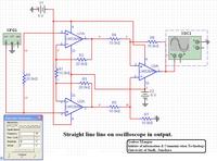
Added after 18 minutes:

Schematic diagram in high resolution...
 

Re: help needed

I don't have EWB (Electronics WorkBenck right?), but here you have good start for an Instrumentation Amplifier with Operational Amplifiers. You can see in that site an explanation of the purpose of each resistor.

Mangrio said:
Instrumentation amplifier is a differential amplifier so, it takes different input
This means that the amplifier, amplifies the difference betwen the inputs. It has two inputs, V1 and V2, and the output is something like (V2-V1)*k, where k is the amplification factor of the amplifier.

Regards.

Added after 13 minutes:

Mangrio said:
I have tried this one by getting help from some sites.
95_1274892336_thumb.jpg
Try connecting the signal source this way: source signal (+) to U2A pin 3, and the source signal (-) to U1A pin 3.

The problem is that in your circuit you're not amplifying a differential signal, you're amplifying a common mode signal (Is not exactly that, but due the high impendance of the operational amplifiers is something like this). And this type of amplifier, rejects common mode signals, due to the differential input (¿Do you remember that the out is proportional to V2-V1?).

Regards.
 

tried that ... changes the sources too to - and +

but after that it was resulting in squrae wave with amplified signal
 

Your earlier drawing showed a 10V, input signal. Try something a lot smaller - say 10mV.

Keith
 

The problem is the amplification factor, and the voltage of the source, and/or the power supply.
The gain of the differential amplifier is: \[\frac{V_{out}}{V_{2}-V_{1}} = (1+\frac{2*R_{2}}{R_{1}})*\frac{R_{6}}{R_{4}}\], with the resistor values of your circuit you get: \[\frac{V_{out}}{V_{2}-V_{1}} = 4\], the output you will get is: \[V_{out} = 4*({V_{2}-V_{1}})\].

keith1200rs is trying to say is that if you put a source of 10V, you will get an output signal of 40V, and this is greater than your power supply (+5V and -5V, it is 10V). That's the reason of the square wave, the amplifier is saturated, because they can't go outside the limits impossed by the power supply.

To solve this, you can try lowering the amplification factor of the differential amplifier (changing the values of the resistors), or lowering your input signal, or using a greater power supply. ¡What solution is the best?, it depends of your particular situation.

Regards
 
Last edited by a moderator:

Status
Not open for further replies.

Part and Inventory Search

Welcome to EDABoard.com

Sponsor

Back
Top