Continue to Site

Welcome to EDAboard.com

Welcome to our site! EDAboard.com is an international Electronics Discussion Forum focused on EDA software, circuits, schematics, books, theory, papers, asic, pld, 8051, DSP, Network, RF, Analog Design, PCB, Service Manuals... and a whole lot more! To participate you need to register. Registration is free. Click here to register now.

Help needed w.r.t D.A.C and FPGA on Nexsys2 Board!!!

Status
Not open for further replies.

sai1711

Newbie level 5
Joined
Jul 28, 2010
Messages
8
Helped
0
Reputation
0
Reaction score
0
Trophy points
1,281
Activity points
1,353
Hi All,
I got Bazinga'ed by the thing here.
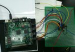
After tinkering around for the past 8 days on my FPGA+ DAC to generate a Sinewave. I am still stuck.
Specs:
128 word deep ROM was used by me on VHDL
Board: Nexsys2

DAC: LTC1668, 16-bit Data In and differential signal IoutA and IoutB

code used:
Code:
  ---------------ROM module------------
  
  library ieee;
use ieee.std_logic_1164.all;
use ieee.std_logic_arith.all;		 
use ieee.std_logic_unsigned.all;

entity ROM is
port(	Clock   : in std_logic;
	Reset	: in std_logic;	
	Enable	: in std_logic;
	Read	: in std_logic;
	Address	: in std_logic_vector(6 downto 0);
	Data_out: out std_logic_vector(15 downto 0)
);
end ROM;

--------------------------------------------------------------

architecture Behav of ROM is

    type ROM_Array is array (0 to 127) 
	of std_logic_vector(15 downto 0);

    constant Content: ROM_Array := (
       
		 
0=>"0000000000000000",
1=>"0000001111011101",
2=>"0000011110111000",
3=>"0000101110001110",
4=>"0000111101011100",
5=>"0001001100100001",
6=>"0001011011011010",
7=>"0001101010000101",
8=>"0001111000011111",
9=>"0010000110100110",
10=>"0010010100011000",
11=>"0010100001110011",
12=>"0010101110110100",
13=>"0010111011011011",
14=>"0011000111100011",
15=>"0011010011001101",
16=>"0011011110010101",
17=>"0011101000111011",
18=>"0011110010111100",
19=>"0011111100010111",
20=>"0100000101001011",
21=>"0100001101010101",
22=>"0100010100110110",
23=>"0100011011101011",
24=>"0100100001110100",
25=>"0100100111001111",
26=>"0100101011111100",
27=>"0100101111111010",
28=>"0100110011001001",
29=>"0100110101100111",
30=>"0100110111010101",
31=>"0100111000010010",
32=>"0100111000011110",
34=>"0100110111111010",
35=>"0100110110100100",
36=>"0100110100011110",
37=>"0100110001101000",
38=>"0100101110000001",
39=>"0100101001101011",
40=>"0100100100100111",
41=>"0100011110110101",
42=>"0100011000010110",
43=>"0100010001001011",
44=>"0100001001010101",
45=>"0100000000110110",
46=>"0011110111101111",
47=>"0011101110000000",
48=>"0011100011101101",
49=>"0011011000110101",
50=>"0011001101011100",
51=>"0011000001100011",
52=>"0010110101001011",
53=>"0010101000010111",
54=>"0010011011001001",
55=>"0010001101100010",
56=>"0001111111100101",
57=>"0001110001010100",
58=>"0001100010110001",
59=>"0001010011111111",
60=>"0001000101000000",
61=>"0000110101110110",
62=>"0000100110100011",
63=>"0000010111001011",
64=>"0000000111101111",
65=>"1111111000010001",
66=>"1111101000110101",
67=>"1111011001011101",
68=>"1111001010001010",
69=>"1110111011000000",
70=>"1110101100000001",
71=>"1110011101001111",
72=>"1110001110101100",
73=>"1110000000011011",
74=>"1101110010011110",
75=>"1101100100110111",
76=>"1101010111101001",
77=>"1101001010110101",
78=>"1100111110011101",
79=>"1100110010100100",
80=>"1100100111001011",
81=>"1100011100010011",
82=>"1100010010000000",
83=>"1100001000010001",
84=>"1011111111001010",
85=>"1011110110101011",
86=>"1011101110110101",
87=>"1011100111101010",
88=>"1011100001001011",
89=>"1011011011011001",
90=>"1011010110010101",
91=>"1011010001111111",
92=>"1011001110011000",
93=>"1011001011100010",
94=>"1011001001011100",
95=>"1011001000000110",
96=>"1011000111100010",
97=>"1011000111101110",
98=>"1011001000101011",
99=>"1011001010011001",
100=>"1011001100110111",
101=>"1011010000000110",
102=>"1011010100000100",
103=>"1011011000110001",
104=>"1011011110001100",
105=>"1011100100010101",
106=>"1011101011001010",
107=>"1011110010101011",
108=>"1011111010110101",
109=>"1100000011101001",
110=>"1100001101000100",
111=>"1100010111000101",
112=>"1100100001101011",
113=>"1100101100110011",
114=>"1100111000011101",
115=>"1101000100100101",
116=>"1101010001001100",
117=>"1101011110001101",
118=>"1101101011101000",
119=>"1101111001011010",
120=>"1110000111100001",
121=>"1110010101111011",
122=>"1110100100100110",
123=>"1110110011011111",
124=>"1111000010100100",
125=>"1111010001110010",
126=>"1111100001001000",
--127=>"1111110000100011",
--128=>"0000000000000000"
--63=>"0000000000000000",


	OTHERS => "1111110000100011"
	);       

begin
    process(Clock, Reset, Read, Address)
    begin
        if( Reset = '1' ) then
	    Data_out <= "ZZZZZZZZZZZZZZZZ";
        elsif( Clock'event and Clock = '1' ) then
	    if Enable = '1' then
		if( Read = '1' ) then
		    Data_out <= Content(conv_integer(Address));
            	else
                    Data_out <= "ZZZZZZZZZZZZZZZZ";
            	end if;
	    end if;
        end if;
    end process;
end Behav;

-----------------------------------------------------------
--------------------------------------------------counter module to count 4-bit address------
 library ieee ;
use ieee.std_logic_1164.all;
use ieee.std_logic_unsigned.all;

----------------------------------------------------

entity counter is

 port(	clock:	in std_logic;
	rst:	in std_logic;
	count:	in std_logic;
	Q:	out std_logic_vector(6 downto 0)
);
end counter;

----------------------------------------------------

architecture behv of counter is		 	  
	
    signal Pre_Q: std_logic_vector(6 downto 0);

begin

    -- behavior describe the counter

    process(clock, count, rst)
    begin
	if rst = '1' then
 	    Pre_Q <= "0000000";
	elsif (rising_edge(clock) and rst='0') then
	    if count = '1' then
		Pre_Q <= Pre_Q + '1';
	    end if;
	end if;
    end process;	
	
    -- concurrent assignment statement
    Q <= Pre_Q;

end behv;
-------------------------------------------- clock---------------------------

library IEEE;
use IEEE.STD_LOGIC_1164.ALL;

entity clk1mHz is
    Port (
        clk : in  STD_LOGIC;
        reset  : in  STD_LOGIC;
        clk_out: out STD_LOGIC
    );
end clk1mHz;

architecture Behavioral of clk1mHz is
    signal temporal: STD_LOGIC;
    signal counter : integer range 0 to 26 := 0;
begin
    frequency_divider: process (reset, clk) begin
        if (reset = '1') then
            temporal <= '0';
            counter <= 0;
        elsif rising_edge(clk) then
            if (counter = 26) then
                temporal <= NOT(temporal);
                counter <= 0;
            else
                counter <= counter + 1;
            end if;
        end if;
    end process;
    
    clk_out <= temporal;
end Behavioral;


--------------------------------------------------------------------MAIN MODULE-------------------------------------------------------
library IEEE;
use IEEE.STD_LOGIC_1164.ALL;

use IEEE.NUMERIC_STD.ALL;
entity sinecounter is

port (clk,reset,resetclk,rst,En,read,count: in std_logic;
clk_out: out std_logic;
sine: out std_logic_vector(15 downto 0));


end sinecounter;
architecture Behavioral of sinecounter is

component counter is

port(	clock:	in std_logic;
	rst:	in std_logic;
	count:	in std_logic;
	Q:	out std_logic_vector(6 downto 0)
);
end component;


component clk1mHz is
    Port (
        clk : in  STD_LOGIC;
        reset  : in  STD_LOGIC;
        clk_out: out STD_LOGIC
    );
end component;

component ROM is
port(	Clock   : in std_logic;
	Reset	: in std_logic;	
	Enable	: in std_logic;
	Read	: in std_logic;
	Address	: in std_logic_vector(6 downto 0);
	Data_out: out std_logic_vector(15 downto 0)
);
end component;
 
signal tempo: std_logic_vector(6 downto 0);
begin

x1: counter port map( clock=>clk, count=>count, rst=>rst,Q=>tempo);

x2: clk1mHz port map ( clk=> clk, reset=>resetclk, clk_out=> clk_out);

x3: ROM port map(Clock=>clk, Reset=> reset, Enable=> En, Read=>read, Address=> tempo, Data_out=> sine);
			 
end Behavioral;

UCF file :
Code:
Net "clk" Loc ="B8";
Net "sine(0)" Loc ="J13";
Net "sine(1)" Loc="M18"; 
Net "sine(2)" Loc="N18"; 
Net "sine(3)" Loc="P18";
 
Net "sine(4)" Loc="G15"; 
Net "sine(5)" Loc="J16"; 
Net "sine(6)" Loc="G13"; 
Net "sine(7)" Loc="H16"; 

Net "sine(8)" Loc="M13"; 
Net "sine(9)" Loc="R18"; 
Net "sine(10)" Loc="R15"; 
Net "sine(11)" Loc="T17";
 
Net "sine(12)" Loc="L15"; 
Net "sine(13)" Loc="K12"; 
Net "sine(14)" Loc="L17"; 
Net "sine(15)" Loc="M15";
 
Net "clk_out" Loc="H15";
Net "reset" Loc="G18";
Net "resetclk" Loc="H18";
Net "rst" Loc="K18";
Net "En" Loc="K17";
Net "read" Loc="L14";
Net "count" Loc="L13";


DAC Output
dig1.JPG
digi2.JPG
 

Hi All,
I got Bazinga'ed by the thing here.
After tinkering around for the past 8 days on my FPGA+ DAC to generate a Sinewave. I am still stuck.
Specs:
128 word deep ROM was used by me on VHDL
Board: Nexsys2

DAC: LTC1668, 16-bit Data In and differential signal IoutA and IoutB

code used:
Code:
  ---------------ROM module------------
  
  library ieee;
use ieee.std_logic_1164.all;
use ieee.std_logic_arith.all;		 
use ieee.std_logic_unsigned.all;

entity ROM is
port(	Clock   : in std_logic;
	Reset	: in std_logic;	
	Enable	: in std_logic;
	Read	: in std_logic;
	Address	: in std_logic_vector(6 downto 0);
	Data_out: out std_logic_vector(15 downto 0)
);
end ROM;

--------------------------------------------------------------

architecture Behav of ROM is

    type ROM_Array is array (0 to 127) 
	of std_logic_vector(15 downto 0);

    constant Content: ROM_Array := (
       
		 
0=>"0000000000000000",
1=>"0000001111011101",
2=>"0000011110111000",
3=>"0000101110001110",
4=>"0000111101011100",
5=>"0001001100100001",
6=>"0001011011011010",
7=>"0001101010000101",
8=>"0001111000011111",
9=>"0010000110100110",
10=>"0010010100011000",
11=>"0010100001110011",
12=>"0010101110110100",
13=>"0010111011011011",
14=>"0011000111100011",
15=>"0011010011001101",
16=>"0011011110010101",
17=>"0011101000111011",
18=>"0011110010111100",
19=>"0011111100010111",
20=>"0100000101001011",
21=>"0100001101010101",
22=>"0100010100110110",
23=>"0100011011101011",
24=>"0100100001110100",
25=>"0100100111001111",
26=>"0100101011111100",
27=>"0100101111111010",
28=>"0100110011001001",
29=>"0100110101100111",
30=>"0100110111010101",
31=>"0100111000010010",
32=>"0100111000011110",
34=>"0100110111111010",
35=>"0100110110100100",
36=>"0100110100011110",
37=>"0100110001101000",
38=>"0100101110000001",
39=>"0100101001101011",
40=>"0100100100100111",
41=>"0100011110110101",
42=>"0100011000010110",
43=>"0100010001001011",
44=>"0100001001010101",
45=>"0100000000110110",
46=>"0011110111101111",
47=>"0011101110000000",
48=>"0011100011101101",
49=>"0011011000110101",
50=>"0011001101011100",
51=>"0011000001100011",
52=>"0010110101001011",
53=>"0010101000010111",
54=>"0010011011001001",
55=>"0010001101100010",
56=>"0001111111100101",
57=>"0001110001010100",
58=>"0001100010110001",
59=>"0001010011111111",
60=>"0001000101000000",
61=>"0000110101110110",
62=>"0000100110100011",
63=>"0000010111001011",
64=>"0000000111101111",
65=>"1111111000010001",
66=>"1111101000110101",
67=>"1111011001011101",
68=>"1111001010001010",
69=>"1110111011000000",
70=>"1110101100000001",
71=>"1110011101001111",
72=>"1110001110101100",
73=>"1110000000011011",
74=>"1101110010011110",
75=>"1101100100110111",
76=>"1101010111101001",
77=>"1101001010110101",
78=>"1100111110011101",
79=>"1100110010100100",
80=>"1100100111001011",
81=>"1100011100010011",
82=>"1100010010000000",
83=>"1100001000010001",
84=>"1011111111001010",
85=>"1011110110101011",
86=>"1011101110110101",
87=>"1011100111101010",
88=>"1011100001001011",
89=>"1011011011011001",
90=>"1011010110010101",
91=>"1011010001111111",
92=>"1011001110011000",
93=>"1011001011100010",
94=>"1011001001011100",
95=>"1011001000000110",
96=>"1011000111100010",
97=>"1011000111101110",
98=>"1011001000101011",
99=>"1011001010011001",
100=>"1011001100110111",
101=>"1011010000000110",
102=>"1011010100000100",
103=>"1011011000110001",
104=>"1011011110001100",
105=>"1011100100010101",
106=>"1011101011001010",
107=>"1011110010101011",
108=>"1011111010110101",
109=>"1100000011101001",
110=>"1100001101000100",
111=>"1100010111000101",
112=>"1100100001101011",
113=>"1100101100110011",
114=>"1100111000011101",
115=>"1101000100100101",
116=>"1101010001001100",
117=>"1101011110001101",
118=>"1101101011101000",
119=>"1101111001011010",
120=>"1110000111100001",
121=>"1110010101111011",
122=>"1110100100100110",
123=>"1110110011011111",
124=>"1111000010100100",
125=>"1111010001110010",
126=>"1111100001001000",
--127=>"1111110000100011",
--128=>"0000000000000000"
--63=>"0000000000000000",


	OTHERS => "1111110000100011"
	);       

begin
    process(Clock, Reset, Read, Address)
    begin
        if( Reset = '1' ) then
	    Data_out <= "ZZZZZZZZZZZZZZZZ";
        elsif( Clock'event and Clock = '1' ) then
	    if Enable = '1' then
		if( Read = '1' ) then
		    Data_out <= Content(conv_integer(Address));
            	else
                    Data_out <= "ZZZZZZZZZZZZZZZZ";
            	end if;
	    end if;
        end if;
    end process;
end Behav;

-----------------------------------------------------------
--------------------------------------------------counter module to count 4-bit address------
 library ieee ;
use ieee.std_logic_1164.all;
use ieee.std_logic_unsigned.all;

----------------------------------------------------

entity counter is

 port(	clock:	in std_logic;
	rst:	in std_logic;
	count:	in std_logic;
	Q:	out std_logic_vector(6 downto 0)
);
end counter;

----------------------------------------------------

architecture behv of counter is		 	  
	
    signal Pre_Q: std_logic_vector(6 downto 0);

begin

    -- behavior describe the counter

    process(clock, count, rst)
    begin
	if rst = '1' then
 	    Pre_Q <= "0000000";
	elsif (rising_edge(clock) and rst='0') then
	    if count = '1' then
		Pre_Q <= Pre_Q + '1';
	    end if;
	end if;
    end process;	
	
    -- concurrent assignment statement
    Q <= Pre_Q;

end behv;
-------------------------------------------- clock---------------------------

library IEEE;
use IEEE.STD_LOGIC_1164.ALL;

entity clk1mHz is
    Port (
        clk : in  STD_LOGIC;
        reset  : in  STD_LOGIC;
        clk_out: out STD_LOGIC
    );
end clk1mHz;

architecture Behavioral of clk1mHz is
    signal temporal: STD_LOGIC;
    signal counter : integer range 0 to 26 := 0;
begin
    frequency_divider: process (reset, clk) begin
        if (reset = '1') then
            temporal <= '0';
            counter <= 0;
        elsif rising_edge(clk) then
            if (counter = 26) then
                temporal <= NOT(temporal);
                counter <= 0;
            else
                counter <= counter + 1;
            end if;
        end if;
    end process;
    
    clk_out <= temporal;
end Behavioral;


--------------------------------------------------------------------MAIN MODULE-------------------------------------------------------
library IEEE;
use IEEE.STD_LOGIC_1164.ALL;

use IEEE.NUMERIC_STD.ALL;
entity sinecounter is

port (clk,reset,resetclk,rst,En,read,count: in std_logic;
clk_out: out std_logic;
sine: out std_logic_vector(15 downto 0));


end sinecounter;
architecture Behavioral of sinecounter is

component counter is

port(	clock:	in std_logic;
	rst:	in std_logic;
	count:	in std_logic;
	Q:	out std_logic_vector(6 downto 0)
);
end component;


component clk1mHz is
    Port (
        clk : in  STD_LOGIC;
        reset  : in  STD_LOGIC;
        clk_out: out STD_LOGIC
    );
end component;

component ROM is
port(	Clock   : in std_logic;
	Reset	: in std_logic;	
	Enable	: in std_logic;
	Read	: in std_logic;
	Address	: in std_logic_vector(6 downto 0);
	Data_out: out std_logic_vector(15 downto 0)
);
end component;
 
signal tempo: std_logic_vector(6 downto 0);
begin

x1: counter port map( clock=>clk, count=>count, rst=>rst,Q=>tempo);

x2: clk1mHz port map ( clk=> clk, reset=>resetclk, clk_out=> clk_out);

x3: ROM port map(Clock=>clk, Reset=> reset, Enable=> En, Read=>read, Address=> tempo, Data_out=> sine);
			 
end Behavioral;

UCF file :
Code:
Net "clk" Loc ="B8";
Net "sine(0)" Loc ="J13";
Net "sine(1)" Loc="M18"; 
Net "sine(2)" Loc="N18"; 
Net "sine(3)" Loc="P18";
 
Net "sine(4)" Loc="G15"; 
Net "sine(5)" Loc="J16"; 
Net "sine(6)" Loc="G13"; 
Net "sine(7)" Loc="H16"; 

Net "sine(8)" Loc="M13"; 
Net "sine(9)" Loc="R18"; 
Net "sine(10)" Loc="R15"; 
Net "sine(11)" Loc="T17";
 
Net "sine(12)" Loc="L15"; 
Net "sine(13)" Loc="K12"; 
Net "sine(14)" Loc="L17"; 
Net "sine(15)" Loc="M15";
 
Net "clk_out" Loc="H15";
Net "reset" Loc="G18";
Net "resetclk" Loc="H18";
Net "rst" Loc="K18";
Net "En" Loc="K17";
Net "read" Loc="L14";
Net "count" Loc="L13";


DAC Output
View attachment 97131
View attachment 97132

3 issues i like to raise :

1. sensitivity list : if you are implementing synchronous process then only clk or (async rst_n if you want)
should be written.

2. asertion to 'Z' : you better use iobuffer primitive, and why you actually do this ? (it's not like you have a bi-di bus to drive)

3. you better use the ROM primitive to be on the safe side.

and ofcouse edit this post to include VHDL syntax.

your plot look like some random noise to me, so check you hardware, and scope.
 

Well, it's definitely periodic, but not exactly sine wave. Closer to a triangle wave with superimposed noise...

Anyways, the ever popular question: have you put it through a testbench yet?
 

Well, it's definitely periodic, but not exactly sine wave. Closer to a triangle wave with superimposed noise...

Anyways, the ever popular question: have you put it through a testbench yet?
Yes, its a popular question and everytime has its own local problems. :))
I have not taken it through a TB.
Aftre burning my DAC.
As an alternative I tried the LC-Low pass filter trick. With Delta-sigma thing. Didnt work either.
The Delta sigma module individually is working fine.
The ROM module with counter is individually working fine.
But only when the modules come together, they aint working at all. :(
I am almost at the verge of a certain vexation.
 

How can we know that the DAC is connected correctly? If you verified the data sent to the DAC, it's obviously a hardware problem.

Giving a binary counter output to the DAC would be a simple way to check for correct data line order and complete connection.
 
I would check my power supply and grounding. The wiring looks potentially a bit optimistic. What is the frequency of the clock signal you're sending to that LTC1668? Anyways, I'd make the ground connection between board + DAC a bit beefier and maybe add some bypass caps. Then lower the update frequency and see what we can see on the scope.

That, and double checking a couple of data pins on the DAC with the scope is probably a good idea as well. For that you'd want just a regular binary counter as output, just like FvM suggested. That's easier to watch than bit number 3 of a sine wave for example. ;)
 
Genau, I shall do that today

- - - Updated - - -

The max rated clock frequency of the DAC LTC1668 is 1 MHz. I am feeding in 917 kHz, from the clock divider module. the reason for 128 words deep ROM is the same, i.e. to have a frequency of sampling satisfying nyquist sampling theorem, because with 128 Words and 917 KHz> 2* Freq of the sinewave being generated.

I suspect the wiring to be a culprit too. I shall look to add some caps and see. And I will get back with the outcome.
BTW the Sigma-Delta method posted here: http://designingwithfpgas.blogspot.kr/2011/10/one-of-downfalls-of-fpgas-are-digital.html
http://designingwithfpgas.blogspot.kr/2011_11_01_archive.html

didnt work either.
 

In that case feeding it a 1 kHz clock signal with a simple binary counter would be a nice test. That should then give you a nice slow sawtooth on the scope.

Not sure what the delta-sigma thing has to do with this? That sounds like it's a totally seperated issue from the LTC1668. LTC1668 ==> most likely crap wiring. delta-sigma not working ==> most likely crap coding. ;)

Delta sigma is easy enough to debug though. Just run through a testbench, spit out the 1-bit data stream to text file. Then do some low-pass filtering in your favorite math tool. Matlab, octave, whatever.
 

Status
Not open for further replies.

Part and Inventory Search

Welcome to EDABoard.com

Sponsor

Back
Top