sapphire
Member level 3
Hi All,
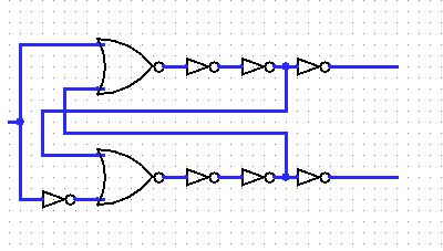
I am designing the non-overlapping clock generation block now for sigma delta ADC. Since our sampling frequency is low (~1MHz) and our technology is fast(0.13um), it's kind of difficult to seperate the clock edges. One way to increase the delay is to use big capacitor on the signal path, but this increase area and current drawn(20uA more). I am thinking a way to reduce the dyamical current that inverter or delay cell can supply. I tried several approaches, but hasn't found a good one. Current-starved inverter needs bias network (10uA for this) and need careful design. Simply increasing channel length causes clock feedthrough and soon direct AC coupling. And some others...I need some help here. I'd like to know if you has any idea that I can borrow.
Thanks in advance
Sapphire