Continue to Site

Welcome to EDAboard.com

Welcome to our site! EDAboard.com is an international Electronics Discussion Forum focused on EDA software, circuits, schematics, books, theory, papers, asic, pld, 8051, DSP, Network, RF, Analog Design, PCB, Service Manuals... and a whole lot more! To participate you need to register. Registration is free. Click here to register now.

[SOLVED] Help need for LM2917 Tachometer Circuit Diagram

Status
Not open for further replies.

vijay s

Full Member level 3
Joined
Jun 14, 2008
Messages
159
Helped
27
Reputation
54
Reaction score
9
Trophy points
1,298
Location
Coimbatore, India
Activity points
2,152
Hai
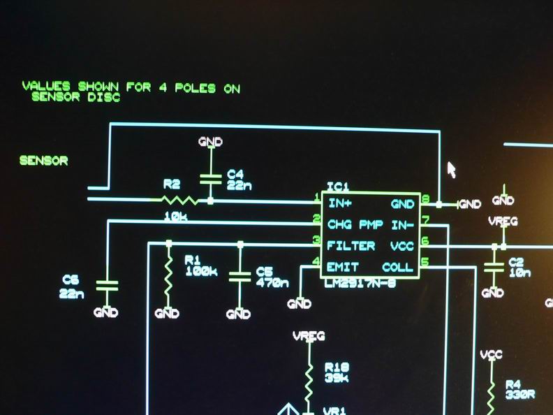
Anybody Got Experienced with LM2917 as Tachometer.. DataSheet Seems to be very Poor... and i want to use 14 pin LM2197 (pulsed DC input)... if anybody has experience in this, please share circuit diagram for 14 pin LM2917....
 

I used the 8 pin one in 1996! It worked fine. All I can see that is different with the 14 pin is 4 NC pins and opamp +input not internally connected to the charge pump and the comparator -input not connected to ground. So with a couple of external links the 14 pin looks like the 8 pin.

Apologies for the low-tech image - the circuit is on DOS Orcad and I couldn't find out how to get a gif out of it. Anyway, that circuit worked!


Keith
 

@keith

is there any limit on Voltage level of Frequency Input... and do above circuit works with AC input or Pulsed DC...
 

Hmmm. Good question! One difference I have just noticed between the 8 pin & 14 pin is that the input on the 8 pin can be +/-28V whereas the 14 pin can only be 0V to 28V. The sensor I used produced positive & negative pulses (an inductive sensor with a toothed wheel). So, for the 14 pin I think you need to arrange for the two inputs to always be biased between 0V and Vcc. With the 8 pin version I used it would tolerate the negative pulses.

The input filtering I used was to filter out noise. It was a motor running around 3000rpm with 4 pulses per rev, so 200Hz. That filter is around 700Hz.

Keith.
 

    vijay s

    Points: 2
    Helpful Answer Positive Rating
here is one page that has what you need i think...

http://www.piclist.com/images/boards/revbar/index.htm

i want to build the same project but as i can find only 8 pin lm2917 i will go with this.


does anyone know what should i change in the schematic to place a 8pin and not 14pin lm2917

sch2.gif
 

For the most part, just substitute the pin numbers:

14pin 8pin
1 1
2 2
3/4 3
5 4
8 5
9 6
10 7
12 8

The problem comes from pin 11. This is biased positive in your diagram because the 14 pin chip cannot have a negative input. The 8 pin version has that internal connection grounded and has to have an signal that goes negative. So, your sensor needs to produce a signal that simply goes around 0V. The circuit I used (see yucky screenshot earlier) was for a magnetic sensor that produced both positive & negative pulses.

If you have something that only produces pulses positive (or negative) with respect to ground you will need to capacitively couple it to pin 1 and put a resistor to ground from pin 1. A capacitor on pin 1 would probably be useful to keep the noise out as well.

Keith.
 

I will take the signal from the coil of the car.. i dont remember now what pulse makes (there we connect all the brand tachometers )


Thanks for the answer my friend :)
 

Hi, this is also my first time using this chip. But i need to know if this chip can convert the frequency in a negative voltage?? i need this to indicate if a dc motor is going clockwise or not, and measure its speed. Thanks for your help
 

Do you mean negative going pulses? The chip cannot detect direction.

Keith.
 

Status
Not open for further replies.

Part and Inventory Search

Welcome to EDABoard.com

Sponsor

Back
Top