liucheng311
Junior Member level 3
dear everyone
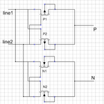
i am going to integrate a full-bridge rectifier in a chip,the rectifier is shown below,line1 and line2 are the two input terminals,and P is the positive output,N is the negative output.this rectifier is used to rectify a DC power supply whose positive wire and negative wire are not identified.
here is my problem: how should i design the ESD protection circuit for the rectifier?since the two wires of the dc power supply are not identified,i can not put the ESD protection circuit between line1 and line2.can anyone help me?
thank you in advance!