Continue to Site

Welcome to EDAboard.com

Welcome to our site! EDAboard.com is an international Electronics Discussion Forum focused on EDA software, circuits, schematics, books, theory, papers, asic, pld, 8051, DSP, Network, RF, Analog Design, PCB, Service Manuals... and a whole lot more! To participate you need to register. Registration is free. Click here to register now.

Help me with my design

Status
Not open for further replies.

2bengg

Junior Member level 3
Joined
Feb 27, 2011
Messages
28
Helped
0
Reputation
0
Reaction score
0
Trophy points
1,281
Activity points
1,498
hello.
i need to make this happen.
i need to know the voltage across the switch at any given time. this voltage needs to be fed to a micro controller.
in theory when a switch is open the entire voltage should appear across it, yes ?
so there is a potential divider connected across the switch to lower the voltage to to 5v.
how ever with the introduction of the relay, i believe this is no longer possible.
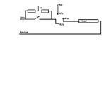
ckt.png

basically the following are the thing that should happen.

1. At any given time, the voltage across the switch should be measurable
2. If the switch is closed the load (say lamp) should glow.
3. Even if the switch is open and it is required that the lamp should glow, it should be possible.
4. If it is required, the circuit should also be able to work so that the load will only glow when the switch is active.

i believe that most of the requirements are taken care of with the circuit that i have attached. except the first one, or am i mistaken ?
Please advice.
thank you.
 

When the switch is open and the relay is open you don't have a divider, you will have 220v instead of 5.
When the switch is closed then you still don't have a divider, you have two resistors in parallel and again 220v instead of 5.

You can't use this kind of connection between a microcontroller and the mains , you have to use some kind of isolation like an optocoupler or a device that is designed to be used directly with the mains and provides an mcu output of some kind.

Alex
 

When the switch is open and the relay is open you don't have a divider, you will have 220v instead of 5.
Yes i realized that, that is exactly the problem i am facing. how can this be rectified ?
[quote[When the switch is closed then you still don't have a divider, you have two resistors in parallel and again 220v instead of 5.[/quote]
when the switch is closed, and say the relay is closed, wouldn't that be a 0 v drop since both the junctions are at the same potential ?
basically i need to two distinct voltage levels. say +5v and 0. so that i can distinguish ON and OFF.
am i missing something in my assumptions ?

You can't use this kind of connection between a microcontroller and the mains , you have to use some kind of isolation like an optocoupler or a device that is designed to be used directly with the mains and provides an mcu output of some kind.
well i wasn't planning on feeding the 5v ac (theoretically, if were to get it) directly to the MC. it would probably end up being fed to an optocoupler or a rectifier before it is fed to MC.

i believe you have understood what it is that i desire to do ?
if you could possibly suggest some other way ? or possibly even link me to something that already exists, i would be very much great full.
 

when the switch is closed, and say the relay is closed, wouldn't that be a 0 v drop since both the junctions are at the same potential ?

Yes the voltage drop is 0v but since this is connected to the 220v line the output will be 220v-0=220v, you don't get 0 volts you get 0 drop and there is a difference in these two.

If you just want to detect if a voltage exists in the input or not then you can connect the diode of an optocoupler using a resistor in parallel with the input.
If you want to detect if the load is turned on then you can connect the optocoupler (with a resistor) in the relay output across the load.

Is this what you want?

Alex
 

i basically want to know if that particular switch is open or closed.
so that i can send a high or a low signal to micro-controller.
so, the micro-controller should be able to recognize, if that switch is open or closed.
 

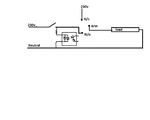
You can connect the resistor and optocoupler diode after the switch (before the relay) from phase to neutral, when the switch is open then the optocoupler will be off, when the switch is on then the optocoupler input will get the 220v and turn on.

Alex
 

and this would not interfere with any of the normal operations ?
like the load would still glow and could still be controller by the relay ?
if it is not too much of a hassle for you, could you possibly give me some kind of rough schematic ? that way i don't screw up.
my project has been delayed and delayed for multiple no of reasons and now i am running out of time :(
 

Something like this
ckt.gif
using an optocoupler like H11AA

Alex
 
  • Like
Reactions: 2bengg

    2bengg

    Points: 2
    Helpful Answer Positive Rating
sorry for the rather late reply, but i have been busy with some personal work.
alex (i hope you see this post)
from what i have found on the net the h11aa optocoupler has a 35v output, i would have to make a divider to feed the Mc would i not ? or am i looking at the wrong parts all together ?
here is a link for the site i found Browse for Products | element14 India
 

The 30v is the minimum Collector to Emitter Breakdown Voltage for the output transistor, the transistor works fine for 5v or 12v, the output is just a transistor it isn't connected anyware internally.
Connect the emitter to the gnd and the collector to a resistor (1k-10K) and the other side of the resistor to the positive supply +5.
Then connect the collector to the mcu input, you will read 5v when opotocoupler is off and 0v when it is on (because the collector output is inverted).

Alex
 
  • Like
Reactions: 2bengg

    2bengg

    Points: 2
    Helpful Answer Positive Rating
thank you for your help alex
 

Status
Not open for further replies.

Part and Inventory Search

Welcome to EDABoard.com

Sponsor

Back
Top