fxhfzy
Newbie level 6
Help for balance amp
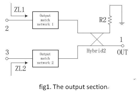
Hello, everyone! I find out a problem when building the balance amp (200W, 57.4-63.6MHz, using LDMOS MRF4300 of Freescale). The output section of the balance amp is shown in fig. 1.
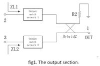
The hybrid has been well tuned with the amplitude unbalance less than 0.1dB and the phase unbalance less than 1°.I use the L-C topology for the output match network. My problem is as follows:
When I built the output match network with the same capacitors and nearly the same wire-wound inductors, I got ZL1= 3.6-j*0.1 which is the right Zload from load-pull simulation by ADS, but meanwhile I got ZL2=3.2-j*0.2.
When I tuned the wire-wound inductors to get ZL1 and ZL2 closer, the amplitude unbalance and the phase unbalance became larger. Finally, when I got ZL2=3.5-j*0.2, The s-parameters of the whole section change to S21=-9.8, S31=-9.0, phase(S21)=-87, phase(31)=-170. The amplitude unbalance is 0.8dB and the phase unbalance is 7°.
The same problem also happens in the input section which is shown in Fig.2, the situation is even worse. If I want to make Zs1 and Zs2 closer, the amplitude unbalance and the phase unbalance of the whole section became as large as 2dB and 14°.
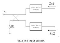
What should I do, to make sure two impedances closer or make the amplitude unbalance and the phase unbalance of the whole section as small as possible?
The eff of the PA is poor (37% at 200W output, the simulation result is 42% at the same output). In my former experiments, I tuned two impedances closer to make sure the gain of two amp is closer, So I think much power may be consumed on R2 due to the large unbalance.
Another question:
How many watts will be consume on R2 if the output power is 200W from your estimation?
Hello, everyone! I find out a problem when building the balance amp (200W, 57.4-63.6MHz, using LDMOS MRF4300 of Freescale). The output section of the balance amp is shown in fig. 1.
The hybrid has been well tuned with the amplitude unbalance less than 0.1dB and the phase unbalance less than 1°.I use the L-C topology for the output match network. My problem is as follows:
When I built the output match network with the same capacitors and nearly the same wire-wound inductors, I got ZL1= 3.6-j*0.1 which is the right Zload from load-pull simulation by ADS, but meanwhile I got ZL2=3.2-j*0.2.
When I tuned the wire-wound inductors to get ZL1 and ZL2 closer, the amplitude unbalance and the phase unbalance became larger. Finally, when I got ZL2=3.5-j*0.2, The s-parameters of the whole section change to S21=-9.8, S31=-9.0, phase(S21)=-87, phase(31)=-170. The amplitude unbalance is 0.8dB and the phase unbalance is 7°.
The same problem also happens in the input section which is shown in Fig.2, the situation is even worse. If I want to make Zs1 and Zs2 closer, the amplitude unbalance and the phase unbalance of the whole section became as large as 2dB and 14°.

What should I do, to make sure two impedances closer or make the amplitude unbalance and the phase unbalance of the whole section as small as possible?
The eff of the PA is poor (37% at 200W output, the simulation result is 42% at the same output). In my former experiments, I tuned two impedances closer to make sure the gain of two amp is closer, So I think much power may be consumed on R2 due to the large unbalance.
Another question:
How many watts will be consume on R2 if the output power is 200W from your estimation?