Continue to Site

Welcome to EDAboard.com

Welcome to our site! EDAboard.com is an international Electronics Discussion Forum focused on EDA software, circuits, schematics, books, theory, papers, asic, pld, 8051, DSP, Network, RF, Analog Design, PCB, Service Manuals... and a whole lot more! To participate you need to register. Registration is free. Click here to register now.

Help me with an amplifier diagram

Status
Not open for further replies.

walker5678

Full Member level 3
Joined
May 17, 2006
Messages
179
Helped
7
Reputation
14
Reaction score
3
Trophy points
1,298
Activity points
2,493
Is this method OK?

Hi,

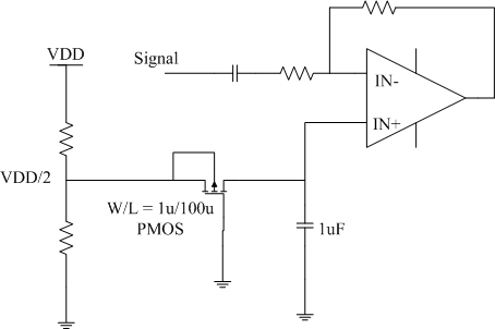
Attached file is an amplifier diagram, in which the IN+ bias voltage is generated by the resistor devider. When there is supply voltage variation, the IN+ will variate, and thus make PSRR bad.

I think about a method to add a W/L=1u/100u PMOS as a large resistor between the 1uF bypass capacitor and the VDD/2, so the variation of bypass capacitor voltage will reduced much, and so as to enhance PSRR performance.


Is this method OK?


thanks


75_1200039386.gif
 

Is this method OK?

what are you going to do about the voltage drop across the PMOS resistor you are proposing... that changes the input voltage right????
 

Is this method OK?

no current is passing through the mos so no drop
 

Is this method OK?

how do you say no current passes through MOS.... there is a path through the MOS and then the capacitor...
 

Is this method OK?

i don't understand what u r saying plz explain it, what i know is that this is a typical low pass filter so at dc the cap is open circuit and no current pass and the Vout is the same as Vin (opamp is a high impedance node), at higher freq. the cap is short and the ripples will be shorted , so the Vout=Vin+the attenuated Vin==Vin
 

Is this method OK?

you are talking theoretically... consider the leakage.... when we go for a large PMOS resistor even that current would count... also given the fact that there is input current of the amp too to worry...

one important thing the user is talking about PSRR... i mean when there is fluctuations in the supply then the capacitor allows current and this leads to the formation of a voltage divider between the capacitor and the PMOS resistor,,.....
 

Is this method OK?

hmmm, he is putting a 1uF cap of course it will give better PSRR!! BTW even if he put a very small cap it will still give a better PSRR.
he is filtering the resistor divider output so all the AC noise will be filtered according to the filter cutoff but it will certainly be better than taking the output directly from the resistor divider
about the leakage he is putting a 1uF cap!! so what value of resistance u think he needs and how much leakage current will be needed to cause voltage drop
regards.
 

Is this method OK?

he is adding a large resistor which itself would add more noise... i believe the capacitor would smoothen out the supply variations a bit... during supply variations there would be considerable variation even if uA of current flows...

i believe the resistor is to be avoided...
 

Re: Is this method OK?

Thanks for your kind comment.

Will the 1u/100u PMOS cause great noise?
The MOS thermal noise equation is 4ktηGm, the Gm of the PMOS is very small, so the thermal noise is small. And the flicker noise equation is K/WLf, the WL of this PMOS is also large, so the flicker noise should be also small.

BTW, the IN+ is a DC bias(or AC ground) of this amplifier, the purpose of my adding this PMOS is to make the voltage of IN+(or the voltage of the 1uF capacitor) more stable.I also think this method is OK, and the simulation also proved it.
 

Is this method OK?

i think method is ok.
 

Is this method OK?

Hi
I can't understand the functionality of PMOS.
just using Cap is sufficient.
regards
 

Is this method OK?

more filtering usually used not to use a large cap
 

Re: Is this method OK?

initial stable condition came after a while ............
 

Re: Is this method OK?

initial stable condition came after a while ............
 

Is this method OK?

the start up time of your filter circuits will be a little bit longer, and I advice you to add a low impedance dc path during start up to establish the dc bias
 

Re: Is this method OK?

Thank you all. It is an audio amplifier circuit, and the 1uF capacitor is an external component outside of the IC.
It do need a start up circuit to establish the DC voltage quickly, and i did not involve this circuit here.

Thanks.
 

Re: Is this method OK?

it is a typical Class-AB amp topology. Maybe the PMOS is not necessary and it is enough to connect the VDD/2 to the input teminal with bypass capacitor.
 

Re: Is this method OK?

The output noise of the voltage divider + lowpass filter with pmos and cap is kT/C. And do not depent on the value of resistances (see T. Lee book for ex.)

You can empoy this circuit. The problem here may be only in that you will get additional temp drift (due to Vgs=f(temp)).
 

Status
Not open for further replies.

Part and Inventory Search

Welcome to EDABoard.com

Sponsor

Back
Top