psrkiran
Newbie level 6
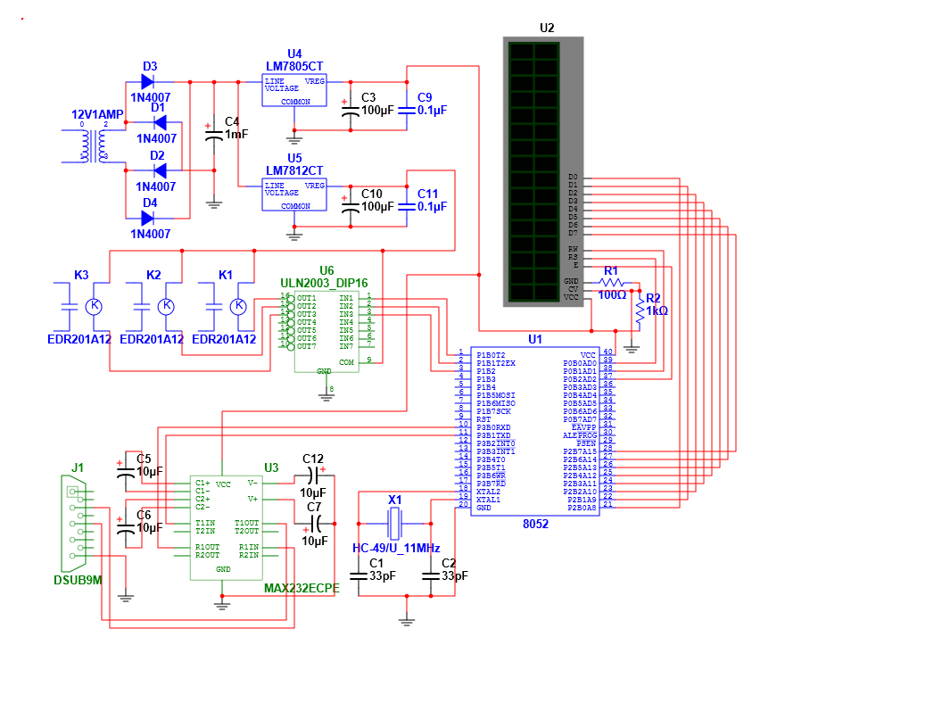
I am attaching the circuit diagram of my project
Serial Communication (MAX232) and LCD are working perfectly
i have so many doubts regarding my circuit
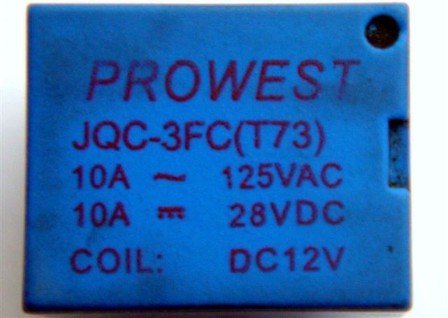
1) is 12v 1 amp transformer is sufficient to drive 3 relays using uln 2003
2) is it mandatory to ground the un used pins of uln 2003
3) in terms of performance, using uln 2003 is recommended or using individual transistors is recommended ( not in terms of cost or easy design )
Problem : some times when i clear P1.1 (relay 2) relay1 is also getting cleared and form there eventhough i set p1.0 (relay 1) it is not taking place why all this happening
please help me
Serial Communication (MAX232) and LCD are working perfectly
i have so many doubts regarding my circuit
1) is 12v 1 amp transformer is sufficient to drive 3 relays using uln 2003
2) is it mandatory to ground the un used pins of uln 2003
3) in terms of performance, using uln 2003 is recommended or using individual transistors is recommended ( not in terms of cost or easy design )
Problem : some times when i clear P1.1 (relay 2) relay1 is also getting cleared and form there eventhough i set p1.0 (relay 1) it is not taking place why all this happening
please help me