Continue to Site

Welcome to EDAboard.com

Welcome to our site! EDAboard.com is an international Electronics Discussion Forum focused on EDA software, circuits, schematics, books, theory, papers, asic, pld, 8051, DSP, Network, RF, Analog Design, PCB, Service Manuals... and a whole lot more! To participate you need to register. Registration is free. Click here to register now.

Help me out with designing a simple LED ramp

Status
Not open for further replies.

Artie

Newbie level 4
Joined
Jan 10, 2008
Messages
5
Helped
0
Reputation
0
Reaction score
0
Trophy points
1,281
Activity points
1,321
led ramp

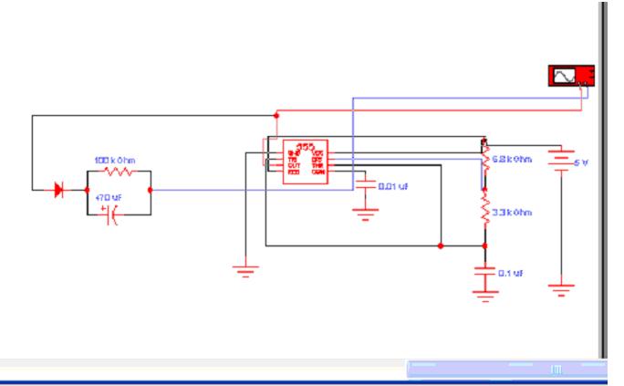
This should be simple, but its eluding me. When I take the input of the circuit "hi", I want the LED brightness to ramp up. When I take it low, I want it to ramp back down. It would be nice if I could use trim-pots to adjust the ramp times separately, but thats not critical. Ramp times should be around 100ms to 1 sec. Having the ramp be linear isn't critical either.

Thanks all.
 

led ramp up

Easy way to do it is to employ a small (8-pin) microcontroller with built-in PWM (pulse-width-modulator) and program it in such a way that when a 'high' is applied to the selected input it starts generating square wave (PWM from 0% to 100% mark-to-space ratio) and when the same input goes low it does the opposite - from 100% to 0% ..

One good candidate for this job is the PICAXE-08M ..
https://corticalcafe.com/hardware_picaxe.htm

Regards,
IanP
 

led ramp circuit

Hey Ian; My initial reaction was to say that that seems like an extraordinarily complex solution to a simple problem. Then I got looking at the link and data closer. Not only does that look like it might be simpler than my original discrete transistor design, but it might even go so far as to take the place of the entire circuit that I'm designing.

Basically, I want three momentary switches to smoothly switch on and off a sequnce of **broken link removed** within a guitar to create a "morphing" of one sound to another rather than an abrupt switch. It also eases the creation of a complex switching matrix.

How appropriate that my axe may be controlled by a PIC-AXE. :wink:

Thanks for the link and the info Ian.

Artie

Edit: By the way, this is what I was toying with originaly. Just not sure of the configuration.
 

multifibrator

using ic 741
replace clock generator with astable multifibrator.
 

ramping led

The time of being hi (for input) is longer than sweeping time .I think you have to use a monostable 555 or a longer sweeping time
 

led ramp gauge

catur_3414 said:
using ic 741
replace clock generator with astable multifibrator.

I'm not sure what that file is, but it opens as just gibberish on my computer. Its just a series of oddball characters.
 

led ramp up circuit

Hi i have a simple idea but i dunno cant it be work or not.
Just connect the input to a diode follow by an resistor then follow
by a parallel capacitor and a LED.
When input 1, the diode will forward bias and starting recharge the capacitor and at the same time ramp up the LED. When the input change from 1 to 0 the diode stop conduct and the capacitor start to discharge and ramp down the LED. Adjust the resistor and capacitor value to adjust the ramp up and ramp down time.
 

ramp up and down led

try to open with ms word.
its work in 4 khz freq.
i'm not sure but replace the R and C may be needed for a lower freq.

Added after 11 minutes:

laststep said:
Hi i have a simple idea but i dunno cant it be work or not.
Just connect the input to a diode follow by an resistor then follow
by a parallel capacitor and a LED.
When input 1, the diode will forward bias and starting recharge the capacitor and at the same time ramp up the LED. When the input change from 1 to 0 the diode stop conduct and the capacitor start to discharge and ramp down the LED. Adjust the resistor and capacitor value to adjust the ramp up and ramp down time.
the led will ramp, but not a linear ramp, coz capacitor charge or discharge is not linear (see the pulse image)
 

simple ramp up down circuit

You are right, the ramp up is not linear. But what i have in mind is try to use the bigger RC so that the charging time to reach maybe 63% is as big as possible so it would seem like linear.
Catur_3414 thx to bring out the point.
 

led ramping

i have try to simulate this design, but the output is same as input (no ramp)
 

Status
Not open for further replies.

Part and Inventory Search

Welcome to EDABoard.com

Sponsor

Back
Top