Continue to Site

Welcome to EDAboard.com

Welcome to our site! EDAboard.com is an international Electronics Discussion Forum focused on EDA software, circuits, schematics, books, theory, papers, asic, pld, 8051, DSP, Network, RF, Analog Design, PCB, Service Manuals... and a whole lot more! To participate you need to register. Registration is free. Click here to register now.

Help me improve the performance of RD15HVF1 UHF amplifier

Status
Not open for further replies.

atlantis7

Member level 2
Joined
Jan 11, 2007
Messages
43
Helped
0
Reputation
0
Reaction score
0
Trophy points
1,286
Activity points
1,745
Hi

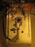
The task is to build a UHF amplifier in the range of 430-440 MHz using the low cost mosfet RD15HVF1. For this device there is no nonlinear model and unfortunately will most likely never be.

A tool called FAST (Fast Amplifier Synthesis Tool) gave me the attached schematic, the power and bias circuit are added by hand.

The problem is that the performance is from bad to worse whatever I do. For the capacitors I used trimmers and also changed them for different ones but whatever I do I can't get an output power of much more than twice the input power.

What's the best way to troubleshoot this? I'm somehow losing the patience with just the trial and error replacing method.

Regards
Martin
 

Re: RD15HVF1 UHF amp

Did you actually try the test cct in the data sheet ?

**broken link removed**

Dave
VK2TDN
 

Re: RD15HVF1 UHF amp

Hi Dave

There once was an evaluation kit for this device from Mitsubishi which contained an evaluation pcb and a software to calculate the component values depending on frequency. Unfortunately they never finished it and in the unfinished condition the software can't calculate UHF frequencies only VHF. Too bad.

However for the first try I used that pcb layout, made a copy of it to not destroy the original. However your suggestion is good as well, in the meantime I made a version as close to the circuit in the datasheet as possible and tried it (therefore it took some time for me to reply). The result is no better; I get out less than I put in, with i.e. 2.8 W in and 1.1 W out this could also be called an active dummy load. The idle current is very high at over 2 amps and seems not to depend on the gate voltage.

Enclosed you find a pic, the length of the microstrips is as in the datasheet, the only difference is that I had no silver plated wire for the coils so used bare ones but that won't cut the mustard will it?

Any ideas? How to proceed?

73
Martin
 

Attachments

  • amp_small.jpg
    amp_small.jpg
    208.3 KB · Views: 191

Re: RD15HVF1 UHF amp

You should be able to turn the quiescent current down to zero with no input signal by adjusting the gate bias voltage. If the current is always high, my guess is it is oscillating. Do you have a spectrum analyser (or maybe even a wavemeter) to check?

Keith.
 

Re: RD15HVF1 UHF amp

Hi Martin,


just an initial quick response its bed time over this side of the world ;) I'm assuming you are running this in the UHF config. ? It appears that you have some filtering on the output. One thing to try would be to initially ignore the filtering and take the output feed straight off the 56pF output cap. bypassing the filtering. just to see if your choice of filter caps and inductors are affecting the tuning of the system.
Also if you are running this at 400 - 500 MHz region what you really cant get away with is the way you are feeding the i/p and o/p connectors to the striplines. lumps of cable from the centrepin to the PCB like that is really not good practice. You would get away with it at HF freqs, even at 50MHz, at 144MHz pushing the friendship a bit ;) at UHF definately not.
You need to mount the centre pins of the connectors at board level and have striplines running right up to the centre pin.

just some initial thoughts will talk more in the new day :) have a ponder on that and tell me your ideas

cheers
Dave
VK2TDN
 

Re: RD15HVF1 UHF amp

As is mentioned before I think your PA is oscillating, most probably due to the layout. You placed the input/output inductors in parallel (getting high mutual coupling), which never should be, even at lower frequencies. They should be perpendicular one to each other, and far away as possible.
Also input and output connectors are relative close to each other, when actually you don't even use a coax shield to the output connector.
 

Re: RD15HVF1 UHF amp

The microstriplines aren't correct..It's not a RF board PCB...
These are looking like CPW rather than MSLines.The distance between line and ground is too close.
Have you ever measured "small signal" gain of the amplifer ??
At especially higher powers substrate and fringe losses are very important.
Review your PCB design.Ground vias are very far and very few,there should be many vias around active device and especially power supply and matching components.
One note .. : Inputs and Outputs can NOT be at the same sides in RF power amplifiers otherwise they can oscillate.

The layout should look like this...
attachment.php
 

Attachments

  • A9R36D5.png
    A9R36D5.png
    127 KB · Views: 694
Last edited:

Re: RD15HVF1 UHF amp

Ok guys, I will need some more precise hints here. You all assume the circuit may be oscillating therefore I guess you will be right.

1. I have access to rapid prototyping equipment and can make a layout similar to the freescale example above with "spread arms" for testing, but the problem is that in the end it has to fit on the size of pcb I took a picture of (Euro size), otherwise it will be of no use to me. Can this be done (shrinked) somehow or should the project be abandoned in this case? Furthermore the connectors need both to be on the front plate in the final design as this has to fit into a standard 19" subrack. One of the connectors could be placed so that the center pin can be soldered to the pcb directly, but not the second one. How should that one be connected?

2. What exact distance between strips and ground should I use?

3. I'm not familiar with the difference between CPW and MS. What exactly needs to be different? Is the main problem that they are bent and not straight?

4. What do you mean with "it's not an rf board pcb"? Do you mean that the design should be improved? Well that's why I'm here to learn from you all. But if you mean that some different board material should be used I'm out of luck, conventional FR4 is all I have.

5. Making more vias should be possible. Let me explain why I didn't in the first place: For prototype boards I have to use rivets for the vias (I have no blackhole or other galvanic through-plating machine). On the back side of the pcb there's the cooler and therefore I put the vias around the cooler because otherwise it won't sit flat on the pcb. However as it seems to be crucial it should be possible to live with that.

Many thanks for the help!

Regards
Martin
 

Re: RD15HVF1 UHF amp

Hey Bigboss,

was trying to find a link to that layout to see if there are dimensions available do you have a link?
would be really helpful for martin. :)

Dave
 

Re: RD15HVF1 UHF amp

AFAIK the lengths and widths of the microstrips depend on the device therefore I think that they might be completely different for that freescale device. For the RD15HVF1 they are in the datasheet. In my posted design the widths and lengths are exactly matching those but I had to bend them and made some other mistakes... Looking forward to your answers.

Martin
 

Re: RD15HVF1 UHF amp

Please reply, I need further help...
 

Re: RD15HVF1 UHF amp

AFAIK the lengths and widths of the microstrips depend on the device therefore I think that they might be completely different for that freescale device. For the RD15HVF1 they are in the datasheet. In my posted design the widths and lengths are exactly matching those but I had to bend them and made some other mistakes... Looking forward to your answers.

Martin

hey martin its not so much the lengths and the widths of the striplines in you unit that were the problem, rather then closeness to the groundplane. Generally the spacing between the stripline and the groundplane would be substantially more than the very fine space in your example. In fact for most stripline work, the groundplane doesnt need to be anywhere near the stripline as in that freescale example by bigboss.

IF you really really must have the input and output lines at the same end of the enclosure then you need to include a vertical screen between those 2 areas running the full length of where any input and output striplines are in parallel. ie. a piece of double sided board soldered along both sides of its lower edge to the groundplane and preferably extending to the internal height of the enclosure.

just a few more thoughts :)

Dave
 

Re: RD15HVF1 UHF amp

I have posted Freescale layout to make you inspired.Of course your layout and physical dimensions will be different.
I will post a simplified layout of your circuit but i used SOT-223 ( An SMD package) instead TO-220 to give you an idea how your layout will look like.
Please note that It's just an illustration, not real layout..


Status
Not open for further replies.

Part and Inventory Search

Welcome to EDABoard.com

Sponsor

Back
Top