Twibs
Newbie level 1
boost converter
I am working on a project to create a DC-DC boost converter to use with solar panel. Neither I nor the teachers here a pros in this department, so it's been bit of trial and error so far. So excuse me if we have some massive errors in our line of though, any help is greatly appreciated.
According to data sheets the Vin(pin J1 on pic) is somewhere around 10-20V depending on the amount of the light and current could be as high as 8A.
We are using Texas Instruments card and LabView programming to create PMW and Maximun-Power-Point-Tracking algorithms. The L1(LA25-NP) is a current sensor to give data to the TI card so we can run our MPPT algorithms. PWM freq is 10kHz.
Here is the schema of the first big board that we did.
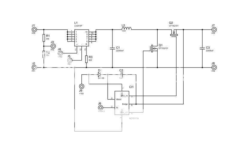
(There should be one pin more above R3 for current information)
We are not yet using the current sensors information but are adjusting the PMW manually. In output we used variable resistor with about 15 ohm value. Q2 has been replaced with diode as in normal boost converter schema. It was transistor earlier since having diode there did some weird stuff to MatLab simulations.
According to simulations this should be fine, but it's just not working properly.
Using about 1mH inductor we created here gives promising results, but the inductor is quickly saturated, at least it is making that high pitching noise. For example with Vin 4V and Iin 1A we get out 6V at 50% duty cycle, but as we increase the duty cycle in Q1 the current start to rise quickly and the equipment limits it to 1A, decreasing the Vin. We have here bigger inductor to use, it's huge variable inductor and by removing the magnetic heart we have still about 100mH value, but with it the Vout is about half of the Vin with 50% Duty cycle. Another mystery to us is why it's not working with it.
According to my own small research, I think we should've used MOSFETs, but I don't think I have enough time to wait for the new components, so we're stuck with IGBTs. Also I know the the capacitors are huge, but they are just what the teachers suggested and had aquired earlier. Although you free to suggest if you think those components are causing the problems.
Also the driver uses the Drv_LO output for the IGBT, so the signal is reversed from PMW for the IGBT.
PMW signal and Output voltage
https://i4.photobucket.com/albums/y107/twibles/F0001TEK.jpg
PMW signal and IGBT Vce
https://i4.photobucket.com/albums/y107/twibles/F0002TEK.jpg
If you need any Oscillosscope pictures or any other info, I will be happy to supply them. Just ask.
I am working on a project to create a DC-DC boost converter to use with solar panel. Neither I nor the teachers here a pros in this department, so it's been bit of trial and error so far. So excuse me if we have some massive errors in our line of though, any help is greatly appreciated.
According to data sheets the Vin(pin J1 on pic) is somewhere around 10-20V depending on the amount of the light and current could be as high as 8A.
We are using Texas Instruments card and LabView programming to create PMW and Maximun-Power-Point-Tracking algorithms. The L1(LA25-NP) is a current sensor to give data to the TI card so we can run our MPPT algorithms. PWM freq is 10kHz.
Here is the schema of the first big board that we did.
(There should be one pin more above R3 for current information)
We are not yet using the current sensors information but are adjusting the PMW manually. In output we used variable resistor with about 15 ohm value. Q2 has been replaced with diode as in normal boost converter schema. It was transistor earlier since having diode there did some weird stuff to MatLab simulations.
According to simulations this should be fine, but it's just not working properly.
Using about 1mH inductor we created here gives promising results, but the inductor is quickly saturated, at least it is making that high pitching noise. For example with Vin 4V and Iin 1A we get out 6V at 50% duty cycle, but as we increase the duty cycle in Q1 the current start to rise quickly and the equipment limits it to 1A, decreasing the Vin. We have here bigger inductor to use, it's huge variable inductor and by removing the magnetic heart we have still about 100mH value, but with it the Vout is about half of the Vin with 50% Duty cycle. Another mystery to us is why it's not working with it.
According to my own small research, I think we should've used MOSFETs, but I don't think I have enough time to wait for the new components, so we're stuck with IGBTs. Also I know the the capacitors are huge, but they are just what the teachers suggested and had aquired earlier. Although you free to suggest if you think those components are causing the problems.
Also the driver uses the Drv_LO output for the IGBT, so the signal is reversed from PMW for the IGBT.
PMW signal and Output voltage
https://i4.photobucket.com/albums/y107/twibles/F0001TEK.jpg
PMW signal and IGBT Vce
https://i4.photobucket.com/albums/y107/twibles/F0002TEK.jpg
If you need any Oscillosscope pictures or any other info, I will be happy to supply them. Just ask.