Continue to Site

Welcome to EDAboard.com

Welcome to our site! EDAboard.com is an international Electronics Discussion Forum focused on EDA software, circuits, schematics, books, theory, papers, asic, pld, 8051, DSP, Network, RF, Analog Design, PCB, Service Manuals... and a whole lot more! To participate you need to register. Registration is free. Click here to register now.

help! Led Matrix Row Transistor

Status
Not open for further replies.

cuber18

Advanced Member level 4
Joined
Sep 4, 2010
Messages
109
Helped
10
Reputation
20
Reaction score
9
Trophy points
1,298
Activity points
1,937
how can a PNP transistor source current for a cathode row led matrix?

my row driver is 74ls138 which is output low and my row ledmatrix is in cathode..
 

Hi,

How may LEDs you wish to connect to a single transistor and what is the system voltage ?

Thanks
 

Your question is not clear, you say you want to source current for a cathode row,
if your connection is to the led cathode then you need to sink current (provide gnd),
source current means to provide positive voltage.

If you want to use a PNP and light a led which is connected to the cathode when the base of the transistor is 0 then you need to connect the led to the emitter and the anode through a resistor to the positive supply,
the collector should be connected to gnd.
Using this circuit you will have about 0.7v to the emitter when the base is 0v (led on) and 5v when the base is 5v (led off).
If your positive power supply to the anode of the led is higher than the one provided in the base then the led will always be on.

Alex
 

how can a PNP transistor source current for a cathode row led matrix?
PNP transistor can only source current from the positive rail down, that is, it can drive anode row/column led matrix ..
The same applies to P-channel mosfets ..

IanP
:wink:
 

if your connection is to the led cathode then you need to sink current (provide gnd),
source current means to provide positive voltage.

I agree with alexan_e
 

If you use a NPN then you can connect the emitter to gnd, drive the base through a resistor (say 1K), connect the collector to the cathode and the anode to a resistor and to the positive supply,
in that case your output will be inverted, led will be on when the base is 5v and off when the base is 0v

Alex
 
ahhmm! my base will be in output low.. thanks for the clear explanation alexan..
 

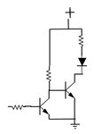
You can also use 2 transistors, the first same as the above NPN but use a resistor 1K connected from the collector to the positive supply (in place of the led+resistor),
then connect a second NPN exactly as the one in my previous post but feed the base resistor from the collector of the first transistor, that way you have 2 inverters and the led will be on with 0v in the first transistor base like you want it.
In that case you can also lower the base resistor of the first transistor to 10K because it will only provide about 5ma in the output.

led_driver.jpg

Alex
 
Last edited:
if i use NPN, whats the value of its current? for example i will use 2N3904, is the collector current = Ic = 200mA? for a 2n2904?
 

if you use 1k in th collector of the first transistor to drive the second base then the base current will be about 5-0.7=4.4v/1k=4.3ma (i assume 5v power supply)
the 2n3904 has a hfe of about 80 so the max output will be 4.3ma * 80 = 344ma
You can always use a lower resistor to drive the base with more current
2n2904 is a PNP , you need a NPN

Alex
 
so the collector current of my 2n3904 will be about 344mA if put a 1k resistor in my collector? :) 2n2904 is 2n3904, just typo error hehehe
 

This is never an exact number because the hfe is given in a range and different transistors will have different hfe, it also changes with temperature.

Alex
 
so how do i calculate collectors current using different kind of transistor..? :)
 

You calculate the base current and then multiply that with the hfe (DC current gain) of the transistor.
To calculate the base current you start with the voltage applied to the base minus about 0.6 or 0.7v voltage drop on the base-emitter diode and also minus the emitter voltage if any and then divide that voltage with the base resistor.

For example, with a resistor of 1k as above and voltage applier to the base 5v you have

5v(base)-0.7v(Vbe)-0(emitter voltage)=4.3v
then using the ohms law you do 4.3v/1000(resistance)=0.0043A (4.3mA)

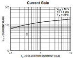
Then you open the datasheet of the transistor and use the hfe data from there, as you will see the datasheet provides min and max hfe for different output current, temperatures, frequency etc.
for example for 2N3904 it says

hfe1.jpg hfe2.jpg

so you select one of the above hfe and you multiply the base current with that to get the max collector current.

Alex
 
i think my base in my output low output.. is it still 5v? or 0v because my base is connected to 74ls138..
 

because my transistors base is connected to a output low voltage of 74ls138.. how it became 5v in your calculations? that seem to bother me sir. .hehe :)
 

When the 0v is applied to the base of the first transistor then that transistor is off and no current is flowing,
because of that the resistor connected from the positive supply to the collector of that transistor works as a pull up resistor and provides 5v to the base of the second transistor.
The second transistor turns on because of that positive voltage in the base.

On the other hand when you apply 5v to the base of the first transistor then it lets current flow (low resistance between emitter and collector) and that creates a voltage drop across the resistor connected between the collector and positive supply, the voltage at the collector will not be 0 because of the min saturation voltage drop across collector and emitter but it will be about 0.7 , even at that voltage the second transistor will not be able to provide any current in the output so the led will be off.

Alex
 
Status
Not open for further replies.

Similar threads

Part and Inventory Search

Welcome to EDABoard.com

Sponsor

Back
Top