Continue to Site

Welcome to EDAboard.com

Welcome to our site! EDAboard.com is an international Electronics Discussion Forum focused on EDA software, circuits, schematics, books, theory, papers, asic, pld, 8051, DSP, Network, RF, Analog Design, PCB, Service Manuals... and a whole lot more! To participate you need to register. Registration is free. Click here to register now.

help in first led project,my first project.

Status
Not open for further replies.

internetuser2k13

Member level 3
Joined
Aug 10, 2013
Messages
56
Helped
0
Reputation
0
Reaction score
0
Trophy points
6
Location
pakistan
Activity points
408
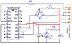
i write my code for blinking LED .
its simulating in proteus .
but i dont know actually connection with PIC18f452.
can anyone help me for that how much voltage required??
here is MCLR
Vdd
Vss
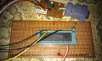
because i want to make this on breadboard..

Thanks..
 
Last edited:

Post project, code and wich compiler used.
 

i used hi-TECH compiler. with MPLAB 8.90.
 

Attachments

  • LED Blink Code For PIC18F452.rar
    59.9 KB · Views: 106

IF you using DIP:

Use a resistor ± 10K and diode from VDD to PIN1... my suggestion!!!
PIN 11 and 32 to VDD = +5V
PIN 12 and 31 to GND = 0V

Proto.png

You has defined 40MHz and simulate 10MHz!!!
 
Last edited:

Hi there,

Try these...
 

Attachments

  • pic16f84-16f84a-16c84-16f628-programmer-circuit.jpg
    pic16f84-16f84a-16c84-16f628-programmer-circuit.jpg
    135.5 KB · Views: 131
  • 30277d.pdf
    4.5 MB · Views: 132
@nagkiller,
i forgetted to change value,
sir what is ICSP in your given diagram.
why you connect it with PIC.please explain this...

Thanks..
 

ICSP (In-Circuit Serial Programming) is used to program pic using Pickit 2 or Pickit 3 programmer... For example.
 
Last edited:
sir i tried on hardware but its not working.
i attached image.
i didnt use external osscilator.
i use diode and resistor for MCLR.
Vdd to 5v. Vss to ground.

and kindly tell me how to check that PIC has burn or not with program.
and how to check that pic has dead or not..
 

Attachments

  • IMAG0075.jpg
    IMAG0075.jpg
    2.7 MB · Views: 112

Check connections, from programmer and proto... In software have option to check after program.
 

software does not verify it.
and also not detect automatically which PIC is connected..
 

Send the back of proto!!!

It seems VPP/MCLR is connected into the PIN2 of mcu!!!

Lapse of memory: I do not remember if using jdm programmer do it in software!!! PICKIT3 do!!!

If using notebook, the jdm programmer not works, because the power of serial... you need a pc with serial port to program device or others programmers or usb programmer...

Which software is using to program device???

And try the Jinzpaul4u schematic and see the doc from microchip (attached pdf).
 
Last edited:

the programmer circuit and PCB layout is attached in this thread in the top.
i am using win pic pgm_1650.
 

Attachments

  • IMAG0084.jpg
    IMAG0084.jpg
    2.6 MB · Views: 119

To program, you need to connect the LVP(PGM)... RB5 = PIN38.

Try adapting your circuit to this:

JDM by Olimex.png

R3 0R is only to add name to pin6 of conector ICSP...

Try too using crystal oscillator...

To know if dead or not, only testing... or using programmer which identify the mcu... i believe!!!!
 

Status
Not open for further replies.

Part and Inventory Search

Welcome to EDABoard.com

Sponsor

Back
Top