Continue to Site

Welcome to EDAboard.com

Welcome to our site! EDAboard.com is an international Electronics Discussion Forum focused on EDA software, circuits, schematics, books, theory, papers, asic, pld, 8051, DSP, Network, RF, Analog Design, PCB, Service Manuals... and a whole lot more! To participate you need to register. Registration is free. Click here to register now.

Help Identify PCB Screw Terminal

Status
Not open for further replies.

with2ls

Junior Member level 3
Joined
Jan 16, 2023
Messages
26
Helped
0
Reputation
0
Reaction score
2
Trophy points
3
Activity points
317
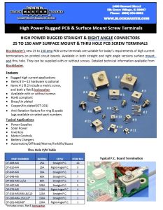
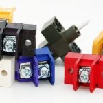
I'm looking for a PCB screw terminal like this (or this exact one):
1677879970917.png


to connect a PCB to a busbar in a high current application. These are from a Meanwell RSP-2000-12.

Typically I would go to Keystone for something like this, but they don't have anything that is:
a. Soldered to the board
b. Reinforced to the board with screws.

Thanks!
 

Yes Keystone is the first name which comes to me :


But no mechanical screw to reinforce

Possibilities upon request here :


See also here :

 
Last edited:

Thanks for the reply, but that's not what I am looking for. I need it to be a "right angle" with both sides threaded.

Or Keystone part number 4334 with legs to solder to the PCB and >100A current capacity.
 

Hi,

It looks like that there is a thread in the bottom hole - where it is mounted on the PCB.
But the other two threads seem to be press fit nuts.
Never seen it done this way.

Würth Elektronik / wurth electronics wave a lot of different screw terminals.
Maybe look at we-online.com.

Btw: did you try a google picture search?

Klaus
 
@KlausST
You're correct on the construction. The metal is 2mm thick and the screw size is 10-24. I did try google lens on it, no luck. I don't need it to be exactly this. This would work, but all I really need is a single 90degree bend.

@FvM
I bet you're right that it's not off the shelf, but I was hoping to find something similar enough to test some ideas. The Ettinger parts may work, let me consider that a little more.

Here are some alternatives I found:
OT-201-M8:
Some combinations of these:


Maybe the fact that I can't find something off the shelf should be a sign that I am taking the wrong approach to solve this problem. I need something to carry a high amount of current between a heavy copper PCB and a battery. Without getting into too many of the details, I was thinking two copper bus bars would a good way to do this, as I also need to "stub" a fer other power converters circuits off of them as well. Here is a quick mockup:
1677967968476.png


The horizontal board is the heavy copper board, and the vertical board is a "low power" control board. Several other power converter circuits would stub into the bus bars horizontally above this. I haven't found a lot of literature on this. Is there a more standardized way of doing this that I am missing?
 

After reading more about the Wurth Redcube Press Fits, it looks like they may be my best option. My original concern with them was joint strength and connection resistance, but according to the docs:
Pressing the pins into the PCB, a high friction between pin and plated through-hole generates a
homogenous cold-welding between the pin and the copper plated via in the PCB. This results in a
gastight, strong mechanical connection with contact resistance less than 200 µOhm. No other
technology transmits currents up to 500 A with such low self-heating.

With regard to long-term reliability, REDCUBE PRESS-FIT is an improvement since it has the lowest
FIT value (Failure in Time) of the overall system. It is up to 30 times better than the FIT value of an SMT
solder joint. A single solid press pin has a typical extraction force of 100 N for 1.6 mm PCB. So a small
component with 8 pins could withstand a weight load of an average person without extraction out of the
PCB.


Thanks,

Phillip
 

Status
Not open for further replies.

Similar threads

Part and Inventory Search

Welcome to EDABoard.com

Sponsor

Back
Top