Welcome to our site! EDAboard.com is an international Electronics Discussion Forum focused on EDA software, circuits, schematics, books, theory, papers, asic, pld, 8051, DSP, Network, RF, Analog Design, PCB, Service Manuals... and a whole lot more! To participate you need to register. Registration is free. Click here to register now.
I designed this circuit in proteus 8 but it doesnt seem to work. Can you tell me what is the problem? And i couldn't find condenser mic anywhere, so i decided to use torch and light dependent resistor. What should i use instead? Please help!
I'm not surprised it doesn't work.
1. Q1 stage is an audio amplifier, the component values do not allow low speed (low frequency) changes in input signal to get through but the LDR is only capable of responding slowly. If you really want to use an LDR, it is probably better connected between the TR pins of the timers directly to ground.
2. Powering U2 from the output of U1 isn't a good idea.
3. U3 seems to be missing ground and VCC connections.
I can't work out what the stages are supposed to do. I would guess both 555s are supposed to trigger simultaneously but the second one wouldn't have any supply until the first one had triggered. Even then, you would be feeding a counter that has no reset so its output might stop high or low almost randomly.
An ordinary hi-fi speaker can be turned into a microphone.
Whatever you use, you need to make it respond quickly to a very brief spike-like signal (handclap). Extreme amplification of a spike, yet rejects room noise.
Maybe Proteus has waveform generators (similar to the battery or a voltage source symbol) and you can write or select a set pulse of a specified voltage at a set time to emulate the electret mic. Piecewise linear in Tina TI is great for creating your own waveforms, Proteus might have this option.
As Brian said, 4017 might need to be clicked on to name/specify power source and gnd.
You could swap the bjt for an op amp amplifier for the condenser mic tiny signal it will produce at the clap, unless the bjt version works well already. Or a comparator to clock the 4017, maybe.
I'd personally remove the first 555 as two looks like an unnecessary extra IC.
As you know, making trigger pulse shorter than output pulse is a 555 requirement. 4017 doesn't care about clock pulse length, so one 555 triggered by a handclap should be enough. Only my opinion.
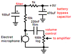
This is interesting for electrets and single-supply OAs, should you ever want such a circuit:
The original circuit shows an electret mic but wrongly calls it a condenser mic.
R1 should be 10k ohms and be fed from an RC filter (1k and 100uF) like this:
This site uses cookies to help personalise content, tailor your experience and to keep you logged in if you register.
By continuing to use this site, you are consenting to our use of cookies.