Continue to Site

Welcome to EDAboard.com

Welcome to our site! EDAboard.com is an international Electronics Discussion Forum focused on EDA software, circuits, schematics, books, theory, papers, asic, pld, 8051, DSP, Network, RF, Analog Design, PCB, Service Manuals... and a whole lot more! To participate you need to register. Registration is free. Click here to register now.

Help !- half bridge false turning ON of MOSFETS

Status
Not open for further replies.

anotherbrick

Full Member level 4
Joined
Jan 10, 2009
Messages
217
Helped
1
Reputation
2
Reaction score
1
Trophy points
1,298
Location
Istanbul , Turkey
Activity points
3,142
hello dear Forum,

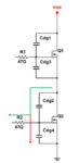
I have designed a 1 KW ultrasonic generator with an half bridge for 28 KHz frequency

however I am facing a problem with false turning ON of IRFP460 mosfets

the H mosfet is driven ON (unwanted peak) when the L mosfet is driven ON (wanted) by IR2113

and vice versa

I have scetched the circuit and mosfet gate signals at attached drawing

what is your advice how can eliminate the unwanted gate signals

thank you

ultrasonic.JPG
 

How do you measure gate voltage? Differential probes? For a reasonable answer you should show a more detailed driver circuit. What's e.g. the value of gate series resistors?
 
hello thank you

I measure gate voltage with digital osciloscope - no diff. probe - I put the probe ground to source of mosfet and the probe tip to gate of mosfet
I measure H and L gate one at a time - no together
I can post a photo of osciloscope screenshot tomorrow
the driver circuit is only an IR2113 with 47 Ohm gate resistor for both L and H mosfets

IR2113 is driven by HCPL4506 optocoupler with 74LS04 inverter between the IR2113 and optocouplers

the mosfets are IRFP460 and the DC blocking cap is 10 uF 400 V bipolar
the piezo elements are 15 x 60 W - 28 KHz
the matching inductor is about 200 uH with air gap
the high frequency transformator is E70 ferrit - turn ratio 1:1

if I cut off 300 V DC link voltage there is no unwanted peaks in gate drives - everything is fine - also if I drive lamps with the generator instead of high freq trafo and piezos there is also no unwanted peaks
 

47 ohm is probably too large to prevent parasitic turn-on due to MOSFET Cirss when the other bridge transistor switch is activated. Either reduce the gate resistor value or place a diode across the gate resistor to keep soft turn on.

Measuring without a differential probe at the highside gate is not recommend in my view.
 
I think the problem is due to a combined effect of the drain-gate capacitance and the large value of gate resistor.
See the attachment showing the parasites.

Consider the instant when Q1 switches ON and Q2 is still OFF... (Assume Vdd = 100V)
Initially the voltage across Q2 was 50V, but when Q1 turns on the voltage will change to 100V.
Now Cdg must charge by additional 50V.
The charging path is through Rg2 and Cgs2. If Cgs is comparable to Cdg and Rg is large, Cgs will charge up and trigger the MOSFET.
For many MOSFETs, Cgs and Cdg are comparable (atleast in order of magnitude)

Selecting a gate resistor value of less than 5 ohm should help.
Additionally, placing an extra 1 or 2nF capacitor across the gate-source terminal should make things even better.

- - - Updated - - -

There's a typo... Cgs is also shown as Cdg.
 

Attachments

  • Picture1.png
    Picture1.png
    47.1 KB · Views: 255
Additionally, placing an extra 1 or 2nF capacitor across the gate-source terminal should make things even better.

The method is used for HV IGBTs (> 2 kV) but rarely helpful for standard MOSFET or IGBT. You better use asymmetric gate drive, as suggested.
 
thank you for all asnwers

I photographed the circuit and the osciloscope screenshots

as suggested by FvM I put a BAT85 shottky diode paralel to gate resitor pointing toward IR2113

here is the gate voltage waveform ( I used isolation transformer for the osciloscope )

there is a 15-20 nanosecond puls at the gate.
is this dangerous ?

will it help if I put a RC filter in front of HIN and LIN inputs of IR2113 ? ( after the LS04 inverter )

thank you

osci.JPG

here is the circuit

kart1.JPG
kart2.JPG

here is the circuit schematic
( the component values are not real circuit values )

ultrasonic2.JPG
ultrasonic3.JPG
 
Last edited:

Filters for the gate driver input signal might be necessary if you experience unwanted switching caused by crosstalk. Examining your circuit (active low open collector opto couplers with 10k pull-up), I think this could easily happen. Dead times must be possibly new determined after inserting the filter.

Your circuit photos shows "flying wires" driving the gates. This setup is rather sensitive to pick up noise by inductive coupling. You'll usually want to drive the gates with gate signal and return wire/trace close together, e.g. as a twisted pair.
 
15ns shouldn't be a problem. ON/OFF delay time will itself be probably more than 15ns.

- - - Updated - - -

I still think placing a small capacitor of around 1nF will reduce the spike width and hight. Many MOSFETs have comparable Cds and Cgs, and this is probably the case here.
 
hello dear friends,

I increased the gate resitor to 100 Ohm and the parasitic peaks at the gates decreased

however I have another problem now

without the uC output the PWM ( both gate signal OFF - inverter standby ) the Mosfets turn on without uC command and a short circuit occurs blowing both mosfets

I suspect there is oscilation at the gates turning on the mosftes

what else can be the reason of self turning on ?
how can I prevent oscilation at the gates ?

thank you
 

when you increased the gate resistor to 100ohm what happened is your mosfet switched slower resulting in lower di/dt which resulted in smaller parasitic injected current in to your gate drive circuit. it makes you happy. but the bad side is your mosfet power dissipation just went up A LOT because it spends too long a time in the linear region.

a 100 ohm gate resistor that "solves" the problem is a clear sign that your gate drive design (schematic and layout) is not good. you might be happy with it cause it "works" but in reality it is a bandage solution.

truly, your problem of false turn on due to that noise glitch is super super common in H-bridge topology. it has been solved in a few ways. typically you start with good archetecture of your design and good layout. these things are CRITICAL for H-bridge topoolgy. probably you do not have the skill to make these things good, so you must rely on the next line of defense. make the power supply bi-polar. turn ON at +12V and turn OFF at -5V. now if you ask mosfet to turn OFF, it is held at -5V. so if you get a 4V nuisance spike.. well, the gate is now at -1V, for sure it is still off. Another solution is to change the gate drive IC to one that has a clamp feature. my favourite is TD350. its nice, and you can use the bootstrap gate drive if you want, or, buy a 0.5W isolated non-regulated power supply ifor $7 nstead which would make your circuit 100x more reliable. failing that.. yes put 100ohm gate drive and make sure your mosfets are not too hot.

just some thoughts.

ps. FVM, nice to see you are still around. of all the power electronic questions, i have seen many of your responses and 100% of them are reliably given. i don't know who you are, but you must be a real pro in the field.
 
Hiii,

I am facing the same problem. I tried all the solutions mentioned here. However, the problem still persists. I made my gate driver to work at +/- 6 V (initially I had +7V and -2V), however, it still turns ON as in the oscilloscope figure mentioned above.

I tried adding the filer too but that doesnt seem to make much of a difference. Can there be any other reason for the same.

Thanks and regards.
 

The problems described in the thread have been brought up by unsuitable component selection, e.g. too large gate series resistor. Without some detail information (MOSFET type, gate driver, series resistor, bus and driver voltage) I'd say, you're apparently making the same fault.
 

The problems described in the thread have been brought up by unsuitable component selection, e.g. too large gate series resistor. Without some detail information (MOSFET type, gate driver, series resistor, bus and driver voltage) I'd say, you're apparently making the same fault.

Dear FvM,

Thanks for the immediate reply. I realised where the problem was. The isolator is generally noisy and I couldnt remove that with the filter too. I included a latch so as to provide blanking times and it works now.

Thanks a lot.
 

your original ckt was probably just OK too, the spikes you saw were noise picked up by your scope, not really on the gate at all....
 

Status
Not open for further replies.

Part and Inventory Search

Welcome to EDABoard.com

Sponsor

Back
Top