Continue to Site

Welcome to EDAboard.com

Welcome to our site! EDAboard.com is an international Electronics Discussion Forum focused on EDA software, circuits, schematics, books, theory, papers, asic, pld, 8051, DSP, Network, RF, Analog Design, PCB, Service Manuals... and a whole lot more! To participate you need to register. Registration is free. Click here to register now.

[SOLVED] Help for Topology and ic selection for DC-DC Converter

Status
Not open for further replies.
A

ats2

Guest
Hello,
I have to desgn 115-305 Vdc input and 28 Volts output 450 Watts DC-DC converter. Can you offer a topology for this application? The input voltage range is wide, it makes difficult to choose a controller.
Thanks.
 

450 W at 28 V makes 16A average.

The efficient method involves a full H-bridge and transformer. Four switching devices chop DC into AC square waves. Send it through a step-down transformer. The secondary carries pulses as great or greater than 16A. Rectify the AC through a diode bridge.

A slightly easier method (although less efficient) is a flyback. A single device switches DC on & off. The pulses go through the primary of a step-down transformer. The secondary needs to carry pulses at 70-80 A, without saturating. Rectify and filter the output
 

Hi,

Look if a flyback topology meets your specifications.

Klaus
 

Please measure the voltage across the 100R resistor feeding the ADC input. Best with

Thank you. But if i am not wrong, flyback is an asymmetrical converter, so storing too much power in the airgap of the power transformer is not possible. Generally advised for below 100W.

Thank you.Do you think when choosing the controller, for a wide range input,115-305 Vdc , just considering minimum and maximum duty cycle and minimum on/off time of controller is enough?
 
Last edited by a moderator:

A 450 watt flyback sounds very unrealistic to me. You might push a flyback to 125 watts. A forward is generally around 250 watts. 450 watts is in the half bridge territory. A full bridge is way overkill.
 

Attachments

  • Topologies power output-cost-efficency-ul-vde.JPG
    Topologies power output-cost-efficency-ul-vde.JPG
    145.1 KB · Views: 150
  • Like
Reactions: ats2

    A

    Points: 2
    Helpful Answer Positive Rating
The way I would tackle this would be a synchronous buck converter to reduce the input voltage to perhaps around a fairly constant 100 volts.
I would then add a chopper circuit that always runs at constant full duty cycle to convert the 100v dc to 28v via a suitable transformer which provides the galvanic isolation.
All the voltage regulation action being carried out by the buck pre regulator.
This is ideal where a very wide input voltage range is expected.

It also hugely simplifies the transformer design, and push pull is not to be despised at lower operating voltages.

The chopper could be a very simple push pull arrangement driven by a flip flop which outputs at half the frequency of the buck regulator, (always at full max duty cycle) with a bit of dead time added.
Because the chopper duty cycle is always at full maximum, the rectifier choke can be made quite small and the output ripple will be minimal.
 
  • Like
Reactions: ats2 and FlapJack

    FlapJack

    Points: 2
    Helpful Answer Positive Rating
    A

    Points: 2
    Helpful Answer Positive Rating
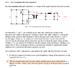
Another possibility is to go for a dual switch forward converter. The required power level should not be a problem.
 

Attachments

  • dual_sw.png
    dual_sw.png
    57.3 KB · Views: 158
  • Like
Reactions: ats2 and FlapJack

    FlapJack

    Points: 2
    Helpful Answer Positive Rating
    A

    Points: 2
    Helpful Answer Positive Rating
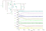
This simulation model shows typical wave-forms and peak currents to expect from this design.
 

Attachments

  • 450W_fwd.png
    450W_fwd.png
    55.6 KB · Views: 160
  • Like
Reactions: ats2

    A

    Points: 2
    Helpful Answer Positive Rating
Another possibility is to go for a dual switch forward converter. The required power level should not be a problem.

2sw forward max duty cycle is limited to 50%. for 300v input-50% and for 115v - 15%, so peak currents increases...
with active clamp forward you can set 66% duty
maybe look at boost to 400V and than LLC half bridge
however, 2sw forward not bad for designer with less experience - is is easy
 

    A

    Points: 2
    Helpful Answer Positive Rating
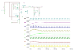
For comparison, here is the wave-forms with reduced duty cycle at 300V line.
 

Attachments

  • 450W_fwd_300V.png
    450W_fwd_300V.png
    55.4 KB · Views: 146

    A

    Points: 2
    Helpful Answer Positive Rating
Status
Not open for further replies.

Similar threads

Part and Inventory Search

Welcome to EDABoard.com

Sponsor

Back
Top