baoer
Newbie level 6
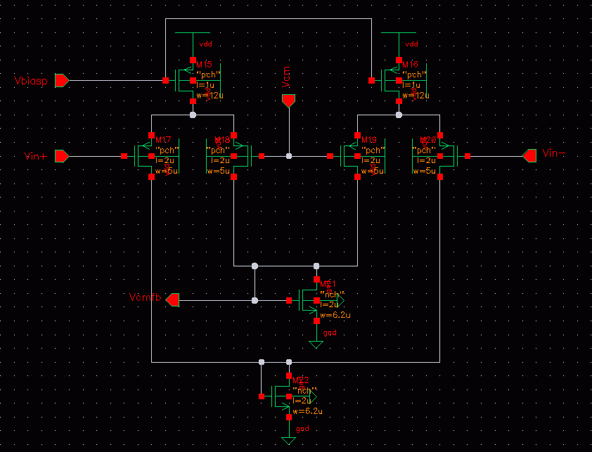
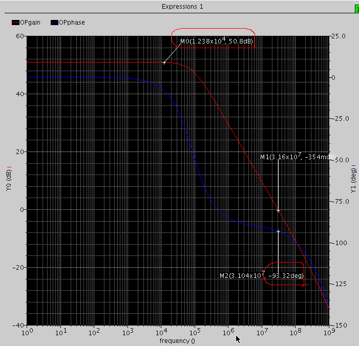
gm-c integrator
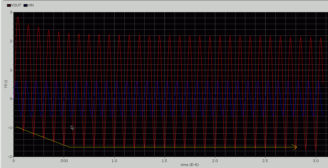
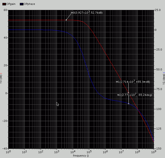
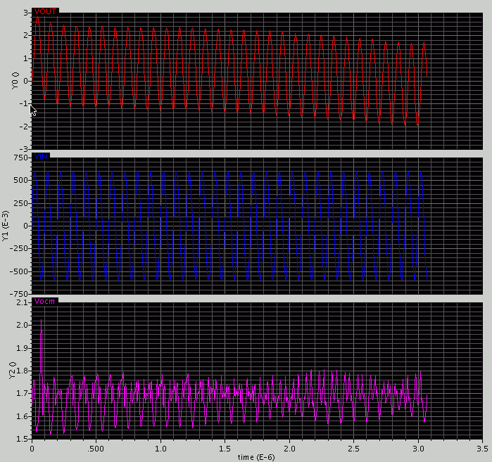
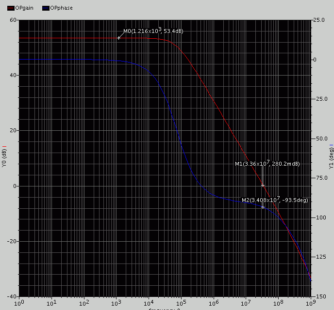
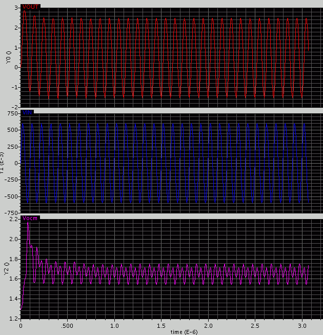
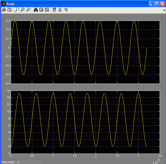
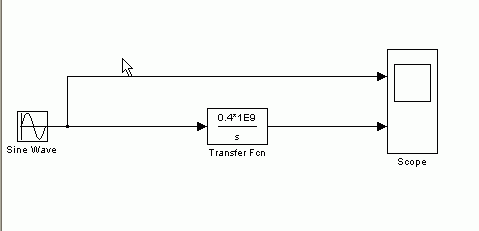
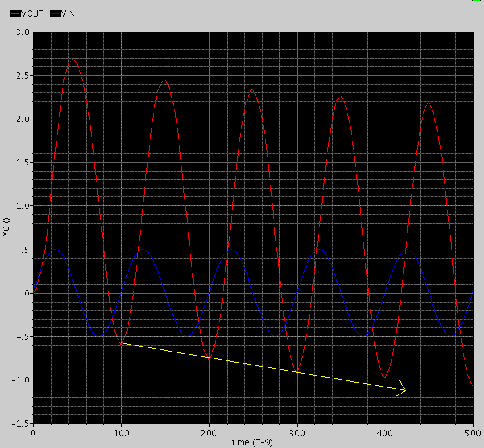
hi everyone, i got a problem with my integrator, my OTA has the 50db gain and 80 phase margin, but it doesn't work like matlab simulation.
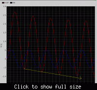
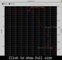
The simulation should above the 0, but it decade down, why????
Does someone help me to solve this problem, plz.
hi everyone, i got a problem with my integrator, my OTA has the 50db gain and 80 phase margin, but it doesn't work like matlab simulation.
The simulation should above the 0, but it decade down, why????
Does someone help me to solve this problem, plz.