Continue to Site

Welcome to EDAboard.com

Welcome to our site! EDAboard.com is an international Electronics Discussion Forum focused on EDA software, circuits, schematics, books, theory, papers, asic, pld, 8051, DSP, Network, RF, Analog Design, PCB, Service Manuals... and a whole lot more! To participate you need to register. Registration is free. Click here to register now.

help diagnose problem with phased array antenna

Status
Not open for further replies.

sarslanali

Junior Member level 2
Joined
Aug 12, 2011
Messages
24
Helped
0
Reputation
0
Reaction score
0
Trophy points
1,281
Activity points
1,505
I designed a four element linear phased array antenna for WIFI for my final year project. I used switched line phase shifter made with Skyworks SPDT rfic. I tested the individual components and they are working fine. Now the problem is that when I attach my phased array with WIFI USB adapter, the signals are received and there is no connectivity problem but the RSSI (Received Signal Strength Indicator) does not change with giving control signals to phase shifters. I simulated everything and everything works when used separately. Can anyone guide me how can I diagnose the problem? My guess is one or two of my RF switch are not working properly. I used 4 switch for one element for phase shifting.

- - - Updated - - -

I also went to measure my radiation pattern. But the facility was new and I think they did not know how to measure phased array when the phase shifting network is also on the same PCB. A microcontroller was also attached to my phased array antenna for control signals. They covered the phase shifting network with Styrofoam, to avoid radiation from it, and put my MCU PCB behind the phased array antenna. They said that they could not measure far field pattern directly because my MCU PCB was also there (because it rotates during measurement), so they measure near field pattern and transformed it to far field. The results were terrible. Even they did not know proper reason. They said it was because my patched my phase shifting network on the antenna PCB as well. Please guide me if there is anything I can do. May be my one or two switches have burnt out. Please help!!!!!!!
 

Can you post an image of the setup that was actually used during the radiation pattern measurements?

Styrofoam is not good to block RF, unless filled with the right concentration of carbon.
 

One source of error in phased arrays is the interaction between the antennas. If they are dipoles, the interaction is great.
 

Sorry I dont have the picture of the setup used for measurement. But they did use Styrofoam with proper amount of carbon.

As for the interaction between the antennas, I used inverted F monopoles. But I used HFSS to simulated the interaction earlier during design phase.

As I have told you I used MCU for controlling the phase shifters. I once noticed a strange voltages on two pins of a phase shifter. On one pin it was 4.8( the 1 or high of MCU) and on the other pin it was 3.5V(where it should have been zero). I don't know the reason for that. But later about 5 minutes (after MCU reset, I think) the voltages were back to normal. Could it be that those RF switches may have been burnt out. How can I tell when a switch is not working?
 

If your input power is below the power rating of the switch, it is unlikely to destroy it due to the RF power. ESD could be a reason.

Can you desolder it and put it in a seperate test fixture and check the insertion loss and isolation?
 

Thanks for reply.
We don't have a separate fixture to test the equipment in our college. But I have enough RF switches to replace the suspected faulty RF switches.
1) Should I replace them and again try with the RSSI experiment I mentioned.

2) I used Wilkinson power divider with measured isolation of -29dB to divide the power into the four elements of the array. Suppose that the first RF switch in the line is not working. Should the corrupt signal or noise from that part should effect the performance of beam steering and how?

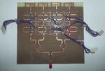
I am uploading the picture of the phased array antenna with the suspected RF switches (on which I was getting 4.8V and 3.5V on DC lines) marked red.

Untitled.jpg
 

Your picture shows an RF PCB, then lots of DC wires connected all over the place. There is quite possibly coupling to those wires, so your RF performance suffers.
 

picture shows messy wire framework there might be some damage in the slots they are fitted

try checking their continuity and thus coupling errors may be reduced
 

If I check their continuity using multimeter, will it hurt the rfic? Is there any other way to reduce the coupling? Actually I couldn't find a way to give the control signals to the phase shifters without cutting a strips in ground plane (I think even that would have degraded the RF performance) . There were 16 control signals. So there are 16 wires. I know its messy wiring but I couldn't find other way. Now I don't have much time to create a new PCB with some other good way for it.

But if the coupling had been an issue, shouldn't there would be working problem with WI-FI? My antenna works with wi-fi, sends and receives signals. Even the RSSI is better than 4dBi gain external antenna. But the only problem is it does not steer it beam pattern.
 

hi
In my idea check the signal path using HF probe and spectrum analyzer if you have anyone available to make sure that the components work properly.this is the first step.If components work properly then check the control data and check the wiring one more time to make sure that they are properly connected.In my opinion the effect of RF signals on DC in your circuit is low because you are in low power.but to make sure about that you can use some kind of ferrite to reduce the noise on your control voltages if your control data are not changed very fast
 

Status
Not open for further replies.

Part and Inventory Search

Welcome to EDABoard.com

Sponsor

Back
Top