Continue to Site

Welcome to EDAboard.com

Welcome to our site! EDAboard.com is an international Electronics Discussion Forum focused on EDA software, circuits, schematics, books, theory, papers, asic, pld, 8051, DSP, Network, RF, Analog Design, PCB, Service Manuals... and a whole lot more! To participate you need to register. Registration is free. Click here to register now.

help !! crystal oscillator

Status
Not open for further replies.

xerxer

Junior Member level 3
Joined
Nov 15, 2005
Messages
29
Helped
0
Reputation
0
Reaction score
0
Trophy points
1,281
Activity points
1,523
oscillator 36.864mhz

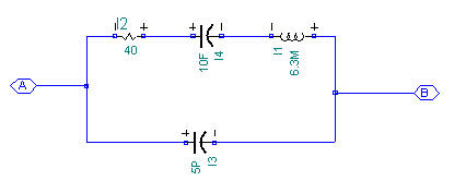
my current project need a 36.864mhz clock source ,i adapt to pierce crystal oscillator to implement .beacuse i haven't design cystal oscillator ,my circuit can't oscillaotr .please give my some adivce ,i need a acutally ciruit preferable .
thanks a lot!
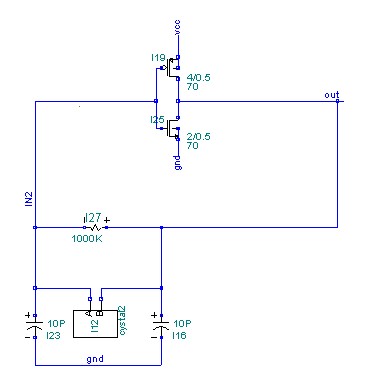
the appendix is my actual schematic.
 

How long do you simulate your circuit?
It may take a long time to oscillate.
 

what about your quartz model? they have initial setting?
 

1) i simulation time is 10ms,i think the time is long enough


i haven't initial setting .i just set the vcc signal as follow:
vcc vcc 0 pwl 0 0 1u 5(hspice)

the cystal model shows below:

1_1174912333.jpg
 

set the initial current of inductor or initial voltage of capacitor to make the circuit oscillate
 

oscillator has a transient interval (some time to reach steady osc.)
 

make sure your circuit's loop gain is larger enough(i.e larger than 20db)
 

What's the funtion of I28,I29 in your schematic?
Used for feedback resistor?
You try to use an ideal resistor and simulate again.
Also ,you can give inductor an intial condition,and check whether the circuit can oscillate.If it can oscillate,then you simulate the circuit again giving VCC a pwl stimulus.
 

Thank you guys a lot.
I've boosted my gain, and the circuit did oscillate. But the frequency I observed was not the one I set. In other words, I wanted a 34Meg wave but got a 70Meg one.
Now I am wondering if my .sp file was not well set. My time step was 1n, and the default option setting was used.

Added after 10 minutes:

And there were something more above my head. I modified my circuit as the pic below, opend the loop and did ac analog with Hspice. Then I found the gain at the wanted frequency was 20dB. But when I simulate the .tran response of this circuit in Hspice, It did not oscillate at all.

Below is the circuit I designed.
93_1174968137.jpg


Added after 5 hours 12 minutes:

i am eager to wait answer online !
 

f≈1/(2*pi*sqrt(LC))

where pi=3.1415926...
L and C is the parameter in your crystal modle.
you can calculate whether it is about the frequency you want.
 

1> make sure you had included the crystal in your open-loop when you simulated open loop gain;
2> add about 1K resistor between out and invertor's output;
3> it seems you used 20Meg crystal??
4> the open loop gain cannot be 20db! too large cause the phase shift not enough.
10~20 maybe comfortable.

5> for quickly run, you can add "ic=0.1mA (or other)" behind the inductor line in your crystal netlist.
 

Status
Not open for further replies.

Similar threads

Part and Inventory Search

Welcome to EDABoard.com

Sponsor

Back
Top