Neuport
Newbie level 4
I have built a pneumatic system that is working well with a wired two button remote with momentary switches to control the piston in and out. I have found a wireless drop-in replacement for my wired switches that wirelessly controls two relays. I have a programmable timer that outputs 5V DC. I would like to interface the timer to the wireless TX to alternately activate the two TX switches. I need a circuit that is triggered by a repeating 5V signal to alternately trigger two relays.
Here is the progress to date.
Current configuration
1. Pressing SW1 momentarily energizes Sol1 with 120Vac releasing air to drive piston right.
2. Pressing SW2 momentarily energizes Sol1 with 120Vac releasing air to drive piston left.

Desired configuration
1. The timer generates a 5.0V DC signal for 0.5 sec in condition one and 0.3 sec in condition two
2. I would like the 5.0V signal to trigger a wireless TX to the RX to alternately control Sol1 or Sol2
3. I would like to manually control the system by pressing SW1 to inject a 5.0V DC signal and trigger the transmission.
4. The range of the wireless link should be reliable to at least 150 feet line-of-sight.

Proposed Solution
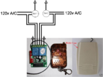
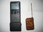
I found a two relay off-the-shelf remote control shown below. It is a drop-in wireless replacement for my wired two switch configuration. However, I still need an interface between the timer and the wireless TX that alternately “presses” buttons A and B with each 5V out of the timer auxiliary jack.

I thought I could do something like shown below. TX Relay A is connected in parallel to TX Switch A and TX Relay B is connected in parallel to TX Switch B. The Timer 5v output is fed to the latching relay coil and common so that each time the 5v signal is sent, the latching relay alternately energizes Relay A or Relay B. However, in researching the latching relay, it appears that I would either need to reverse the current through the relay or use a two coil version and alternately activate the coils.

Any suggestions on how I can make this work or some other way to use a repeating 5V signal to alternately trigger two relays?
Thanks!
Here is the progress to date.
Current configuration
1. Pressing SW1 momentarily energizes Sol1 with 120Vac releasing air to drive piston right.
2. Pressing SW2 momentarily energizes Sol1 with 120Vac releasing air to drive piston left.

Desired configuration
1. The timer generates a 5.0V DC signal for 0.5 sec in condition one and 0.3 sec in condition two
2. I would like the 5.0V signal to trigger a wireless TX to the RX to alternately control Sol1 or Sol2
3. I would like to manually control the system by pressing SW1 to inject a 5.0V DC signal and trigger the transmission.
4. The range of the wireless link should be reliable to at least 150 feet line-of-sight.

Proposed Solution
I found a two relay off-the-shelf remote control shown below. It is a drop-in wireless replacement for my wired two switch configuration. However, I still need an interface between the timer and the wireless TX that alternately “presses” buttons A and B with each 5V out of the timer auxiliary jack.

I thought I could do something like shown below. TX Relay A is connected in parallel to TX Switch A and TX Relay B is connected in parallel to TX Switch B. The Timer 5v output is fed to the latching relay coil and common so that each time the 5v signal is sent, the latching relay alternately energizes Relay A or Relay B. However, in researching the latching relay, it appears that I would either need to reverse the current through the relay or use a two coil version and alternately activate the coils.

Any suggestions on how I can make this work or some other way to use a repeating 5V signal to alternately trigger two relays?
Thanks!

