Continue to Site

Welcome to EDAboard.com

Welcome to our site! EDAboard.com is an international Electronics Discussion Forum focused on EDA software, circuits, schematics, books, theory, papers, asic, pld, 8051, DSP, Network, RF, Analog Design, PCB, Service Manuals... and a whole lot more! To participate you need to register. Registration is free. Click here to register now.

HELP!! Can help me check my dc chopper circuit?

Status
Not open for further replies.
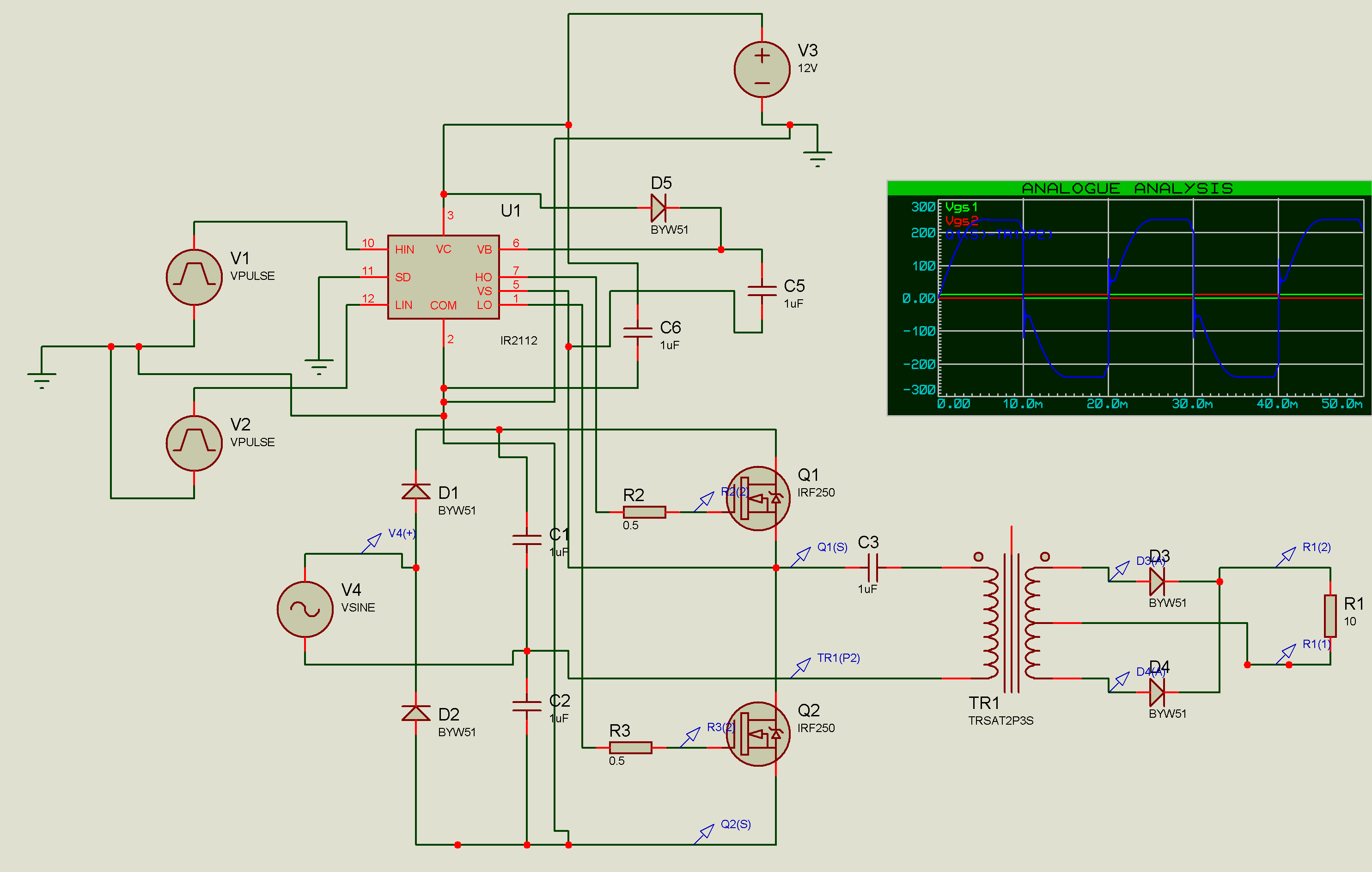
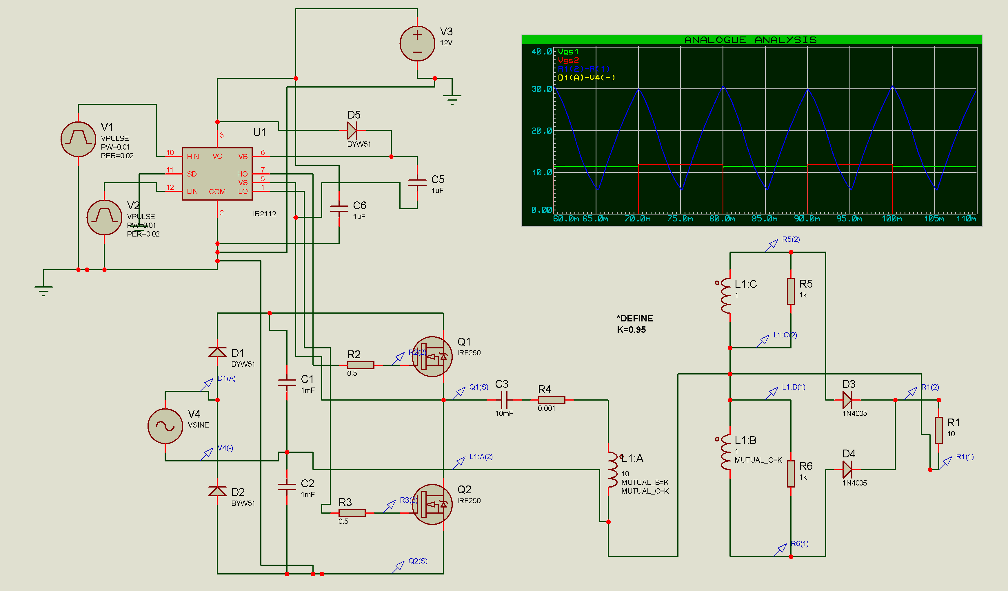
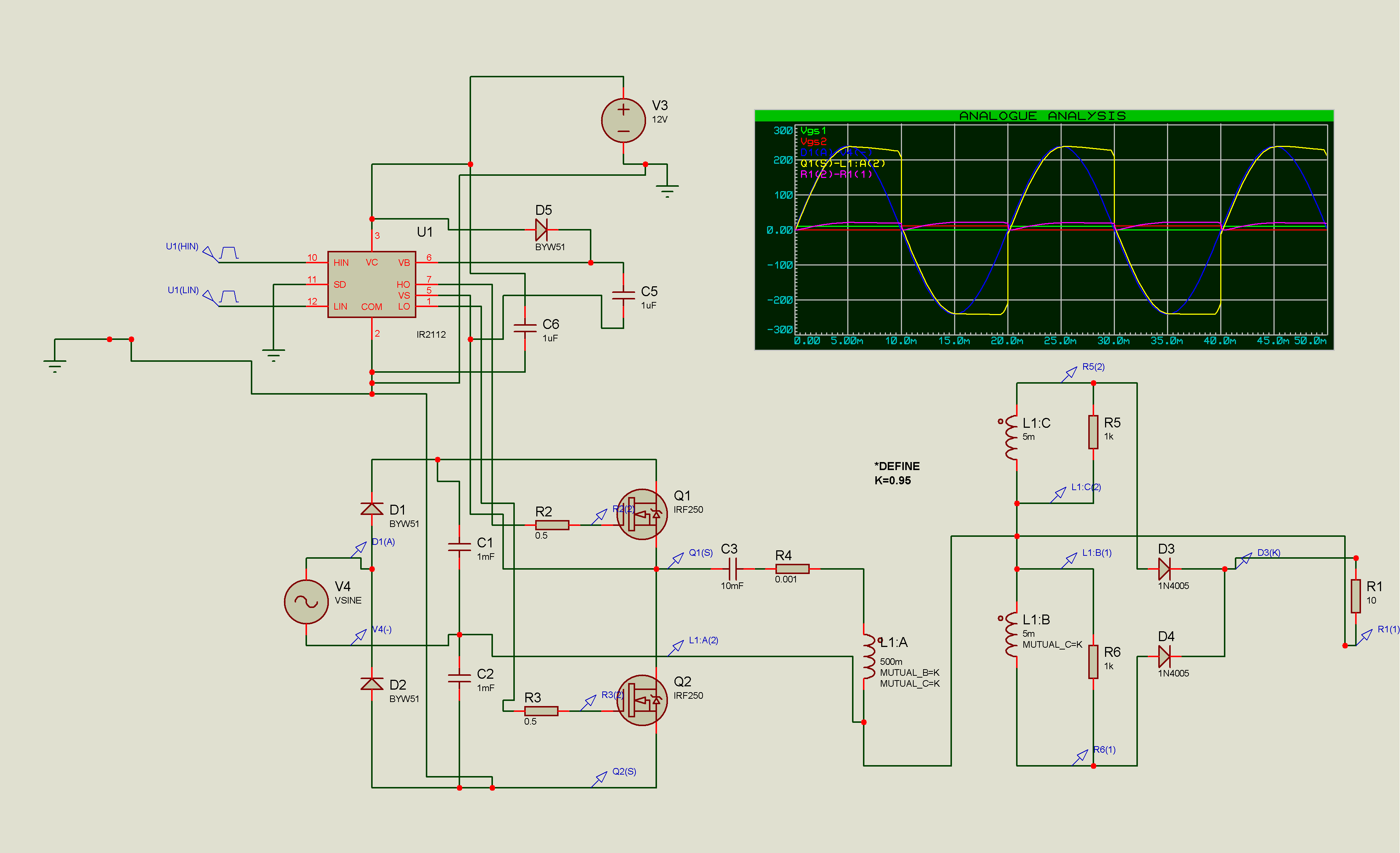
Thank you, Fvm. Actually, I'm quite confuse with grounding part. I'm not so sure where I should ground my circuit. All the while, I thought the negative part of the supply will be ground in a circuit. So, I put a Vsine and ground it at the C2. What is the difference between the symbol for Vsine supply before correction and after correction?


I gues, the only difference is, that I removed the incorrect ground symbol. But you didn't show the input source.
 
Sorry, but I still cannot obtain a full rectification after the going through the transformer.
 

I had changed the transformer. I think it is about grounding problem. There is no problem when I try using only transformer. But when I replaced it into my half bridge circuit, the voltage output at the upper and lower part having the same waveform whereas for actual, they should be opposite.


There are several issues:
- most voltages, that should be measured differentially are apparently measured ground referenced. The circuit grounding itself is correct now.
- you're are operating the chooper at at unusual low frequency
- capacitors C1 - C3, that should have values in a several mf range are dimensioned with 1 uF only
 
you're are operating the chopper at at unusual low frequency
The sine wave is operating at 50Hz. During positive half cycle, the Q1 have to switch on and during negative half cycle Q2 have to switch on. So, I set the pulse frequency to 50Hz.
 

I had tried running with higher frequency, the simulation does not work. So I maintain at 50Hz. I had changed the capacitance values by using the formula c=(i/(2fv)) where v is the ripple voltage. For the f in the equation, which frequency should I refer to. The ac frequency or the switching frequency? I had obtained a full waveform but I don't think this is the correct because the waveform seem like shifted.


After adjusting my values, I obtain a full wave form. Is this correct? Or do I need to run the mosfet at higher frequency?


Hi, i know this thread has been here a long time. I'm trying the same circuit at the moment, but it says time step too small. what could be the possible error there?
 

Increase the PWM to 70-100 KHz , 1mF for C1 & C2 is much too big , use 100uF instead , is C3 for DC block to prevent L1 saturation ? what is your output Voltage and Current requirement, is input 120VAC @ 50Hz ?, notice you are running open loop right now! how did you choose the transformer turns ratio?
 

Status
Not open for further replies.

Part and Inventory Search

Welcome to EDABoard.com

Sponsor

Back
Top